21
Installation: Electrical connection
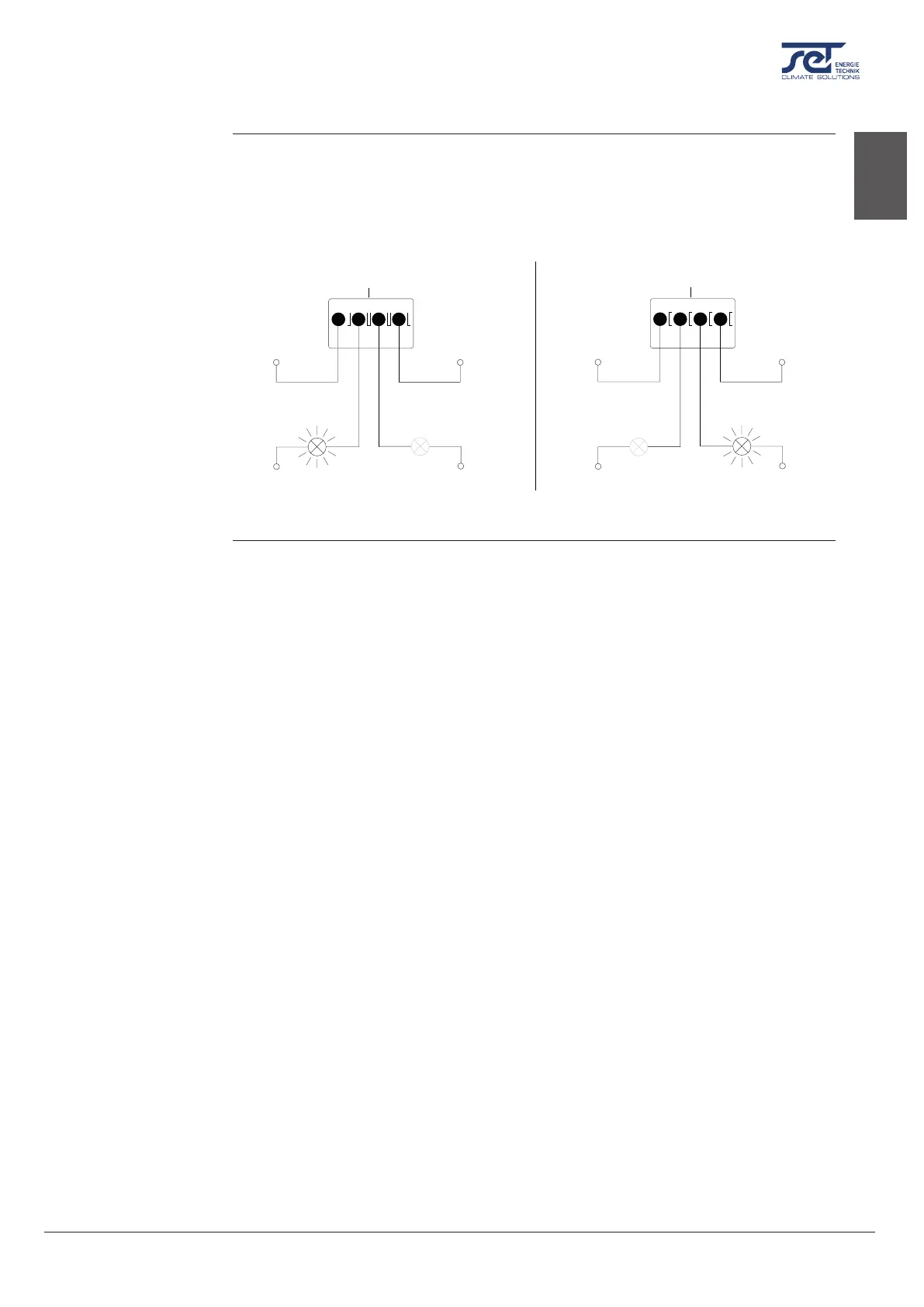
There is an option for connecting an external alarm, which makes it possible to see, when the
dehumidier is operating normally or has an error. In order to use this option you must create
your own external electrical circuit and connect it to the run/fail terminal on the main PCB
(see page 32).
This illustration is an example of how the run/fail circuit could be used.
RUN
FAIL
12
3
4
(Max. 50V, 500mA)
GND
GND
VDC (Max. 50V, 500mA)
RUN
FAIL
12
3
4
VDC (Max. 50V, 500mA)
GND
GND
VDC (Max. 50V, 500mA)
Operational Mode
RUN FAIL
Error Mode
RUN FAIL
Fig. 8
Alarm
Run/ fail
connection
(Optional)
en



 To Next Page