© Setra Systems, Inc. All Rights Reserved. The Setra Systems name and logo are registered trademarks of Setra Systems, Inc.
4. Installation
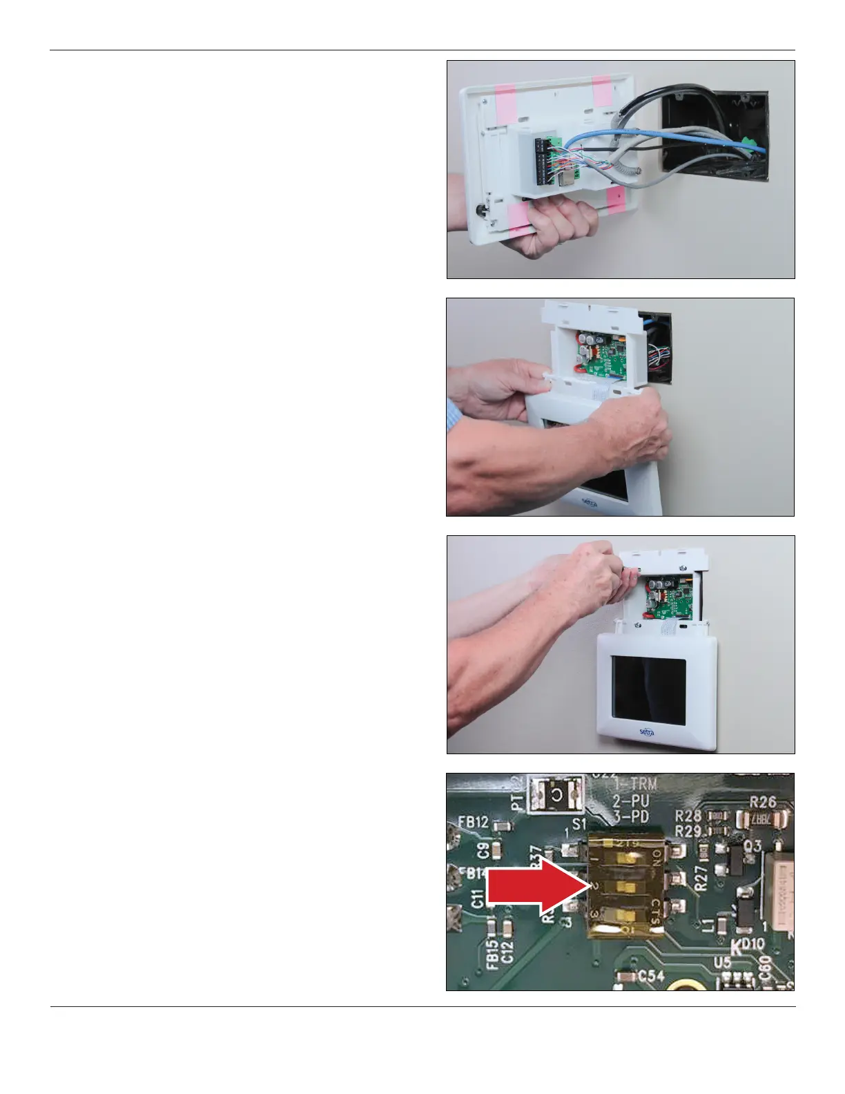
• Make the nal connections by pushing the removable
connectors and wires into the back of the FLEX unit. If
connecting BACnet/IP, insert the RJ-45 cable into the Ethernet
port. If connecting pressure tubing, align HIGH and LOW ports
to their appropriate pressure sensor connections with anti-
kink tubing and secure in place.
• Slide the FLEX unit back into the wall, taking care to not crimp
tubing or damage wires.
• Secure the FLEX base unit into the electrical box with the four
(4) mounting screws provided. Allow the FLEX display to hang
below the mounting box, taking care so that the display does
not get damaged by tools.
• BACnet MS/TP hardware is implemented as isolated RS485.
Wire to Connector COMM, labeled BACNET. Connect TX line
to B (+), RX to A (-) and ground wires to GND. Connect shields
together with wire nut. Hardware conguration is done using a
three position dip switch located in the upper center section of
the rear PCB. Use a small flat blade screwdriver or pen to push
the switch to the right to turn the function on, or to the left to
turn the function off. If the unit will be at the end of the line,
the terminating resistor can be enabled by pushing position
1 to on.