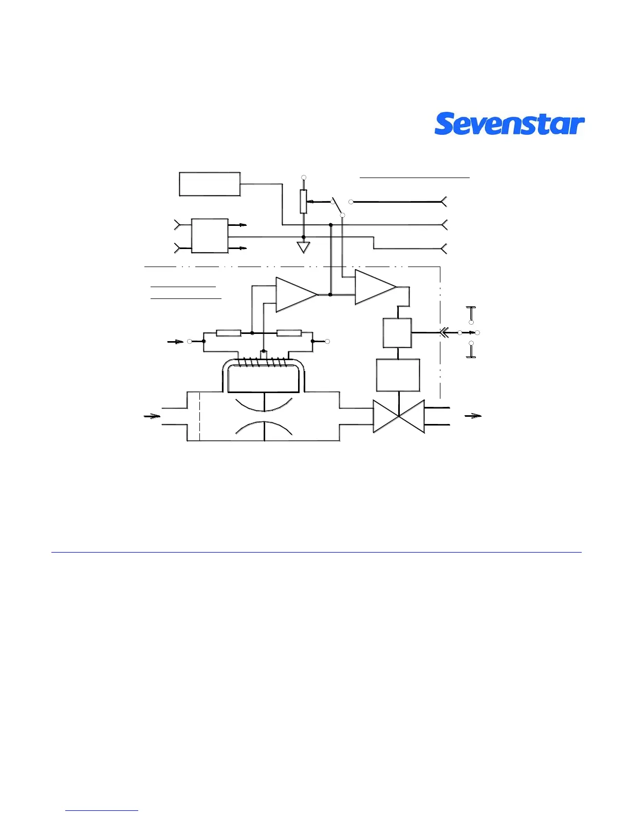
Figure2. Principle of MFC
The outputting flow testing signal from MFC is a direct ratio with the flow through the channels, flow outputting
signal is 0~5VDC. The Flow control ranges of MFC is (2~100) %F.S., flow resolving power is 0.1% F.S..
Attention:
When Valve controller of MFC is posited on position of “PURGE”, it can be functioned as a MFM. In that
case, the maximum flow testing voltage could reach beyond +10V, please be careful, while flow is beyond
F.S. +5V(Full Scale), the real flow will have no linearity corresponding with flow testing voltage. While it’s
purging, flow display will be inaccurate, even showing “reduce” while the real flow is enhanced, please be
sure it’ll be no damaged to device itself.


 To Next Page