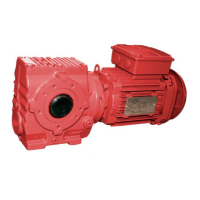
Do you have a question about the SEW-Eurodrive FA47 and is the answer not in the manual?
Details pre-startup checks, direction verification, and anomaly handling.
Checklist for pre-startup activities in potentially explosive atmospheres.
Checklist for essential activities to be performed during the startup process.
Lists necessary tools, equipment, and materials for mechanical installation.
Outlines essential conditions and checks before starting the assembly process.
Guides gear unit installation, including support requirements and screw quality.
Specifies correct tightening torques for various screws in gearmotor installation.
Guides on assembling input/output components using devices and avoiding hammers.
Explains adjusting misalignments and covering moving parts when mounting couplings.
Specifies the allowed ambient temperature range for gearmotors in category II2D.
Explains how temperature classes are determined and indicated for II2G gearmotors.
Details max surface temperatures for II2D units and dust accumulation limits.
Details tightening the retaining screw to the specified torque values.
Details steps for installing shrink disks, including loosening screws and degreasing.
Instructs on applying lubricant to the input shaft for shrink disk installation.
Guides input shaft installation with shrink disk, including collar and gap checks.
First step for TorqLOC® installation: cleaning shaft and hollow shaft.
Instructs on pre-assembling the torque arm without fully tightening screws.
Details securing the bushing with a split ring using specified torques.
Step for sliding the counter bushing onto the customer shaft and hollow shaft.
Final tightening of locking screws with a torque wrench according to the table.
Checking for a minimum gap between outer rings after installation.
Details coupling steps for IEC and NEMA adapters, including shaft cleaning and heating.
Details coupling steps for AQA/AQH adapters, including shaft cleaning and heating.
Tightening screws for AQH type adapters in a specific sequence.
Provides steps for mounting the encoder for speed monitoring.
Safety notes regarding cable routing, line lengths, and shielded cables.
Details mounting motors and adjusting platforms for AD../P covers.
Describes mounting applications using input covers with centering shoulders.
Cleaning bolt threads and applying locking compound for AD../ZR input covers.
Specifies permitted loads for connection screws of AD../ZR input covers.
Instructions for checking the oil level before startup and referencing other sections.
Covers measuring surface and oil temperatures during startup.
Details how to measure surface temperature, maximum load, and temperature difference limits.
Explains measuring oil temperature to determine lubricant change intervals.
Covers startup procedures for different gear unit types, including standalone and inverter-operated.
Guides on installing and adjusting WEX speed monitors, including wiring diagrams.
Details front panel indicators and the RS232 interface for speed monitors.
Illustrates installation of voltage encoders and setting the switching interval.
Notes and hazards to observe before performing inspection or maintenance tasks.
Outlines recommended intervals and tasks for inspection and maintenance.
| Brand | SEW-Eurodrive |
|---|---|
| Model | FA47 |
| Category | Engine |
| Language | English |


