High-Power Stereo Class-D Audio Power Amplifier
SGM4703 with Adjustable Power Limit and Automatic Level Control
11
DECEMBER 2022
SG Micro Corp
www.sg-micro.com
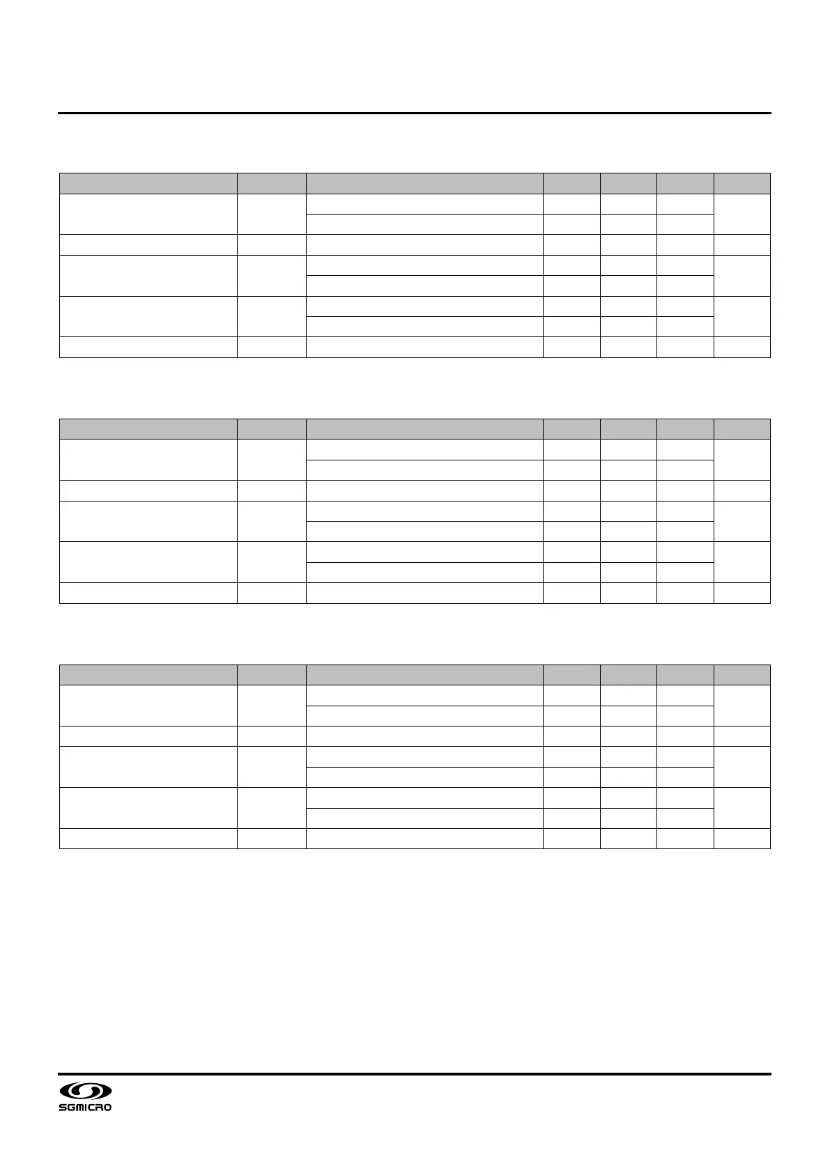
ELECTRICAL CHARACTERISTICS (continued)
(V
DD
= 24V, f = 1kHz, Load = 4Ω + 33μH, SSM, PBTL configuration, T
A
= +25℃, unless otherwise specified.)
PARAMETER SYMBOL CONDITIONS MIN TYP MAX UNITS
Maximum Output Power
(1)
P
O,PEAK
THD+N = 10%, Non-ALC Mode 80
W
THD+N = 1%, Non-ALC Mode 64
ALC Output Power P
O,ALC
V
IN
= 1.0V
RMS
60 W
Total Harmonic Distortion + Noise THD+N
P
O
= 40W, Non-ALC Mode 0.1
%
V
IN
= 1.0V
RMS
, ALC Mode 0.3
Power Efficiency
(2)
η
P
O
= 40W, Non-ALC Mode 90
%
V
IN
= 1.0V
RMS
, ALC Mode 91
Signal-to-Noise Ratio SNR P
O
= 50W, A-weighted 98 dB
(V
DD
= 15V, f = 1kHz, Load = 3Ω + 15μH, SSM, PBTL configuration, T
A
= +25℃, unless otherwise specified.)
PARAMETER SYMBOL CONDITIONS MIN TYP MAX UNITS
Maximum Output Power
(1)
P
O,PEAK
THD+N = 10%, Non-ALC Mode 40
W
THD+N = 1%, Non-ALC Mode 33
ALC Output Power P
O,ALC
V
IN
= 0.60V
RMS
30 W
Total Harmonic Distortion + Noise THD+N
P
O
= 20W, Non-ALC Mode 0.1
%
V
IN
= 0.60V
RMS
, ALC Mode 0.3
Power Efficiency
(2)
η
P
O
= 20W, Non-ALC Mode 89
%
V
IN
= 0.60V
RMS
, ALC Mode 90
Signal-to-Noise Ratio SNR P
O
= 30W, A-weighted 96 dB
(V
DD
= 12V, f = 1kHz, Load = 2Ω + 15μH, SSM, PBTL configuration, T
A
= +25℃, unless otherwise specified.)
PARAMETER SYMBOL CONDITIONS MIN TYP MAX UNITS
Maximum Output Power
(1)
P
O,PEAK
THD+N = 10%, Non-ALC Mode 37
W
THD+N = 1%, Non-ALC Mode 30
ALC Output Power P
O,ALC
V
IN
= 0.50V
RMS
27 W
Total Harmonic Distortion + Noise THD+N
P
O
= 20W, Non-ALC Mode 0.1
%
V
IN
= 0.50V
RMS
, ALC Mode 0.3
Power Efficiency
(2)
η
P
O
= 20W, Non-ALC Mode 87
%
V
IN
= 0.50V
RMS
, ALC Mode 88
Signal-to-Noise Ratio SNR P
O
= 25W, A-weighted 94 dB
NOTES:
1. The peak output power is defined as an instantaneous maximum output power with no consideration of the thermal dissipation capability of the
system board. The maximum continuous output power will be less than the peak output power and largely depend upon the thermal dissipation
capability of the system board.
2. All the power efficiency data are given for a two-side, two-layer printed circuit board and shall be used for reference only. The power efficiency
will be strongly affected by the thermal dissipation capability of the system board, such as the number of layers and the application of a heat sink.