High-Power Stereo Class-D Audio Power Amplifier
SGM4703 with Adjustable Power Limit and Automatic Level Control
4
DECEMBER 2022
SG Micro Corp
www.sg-micro.com
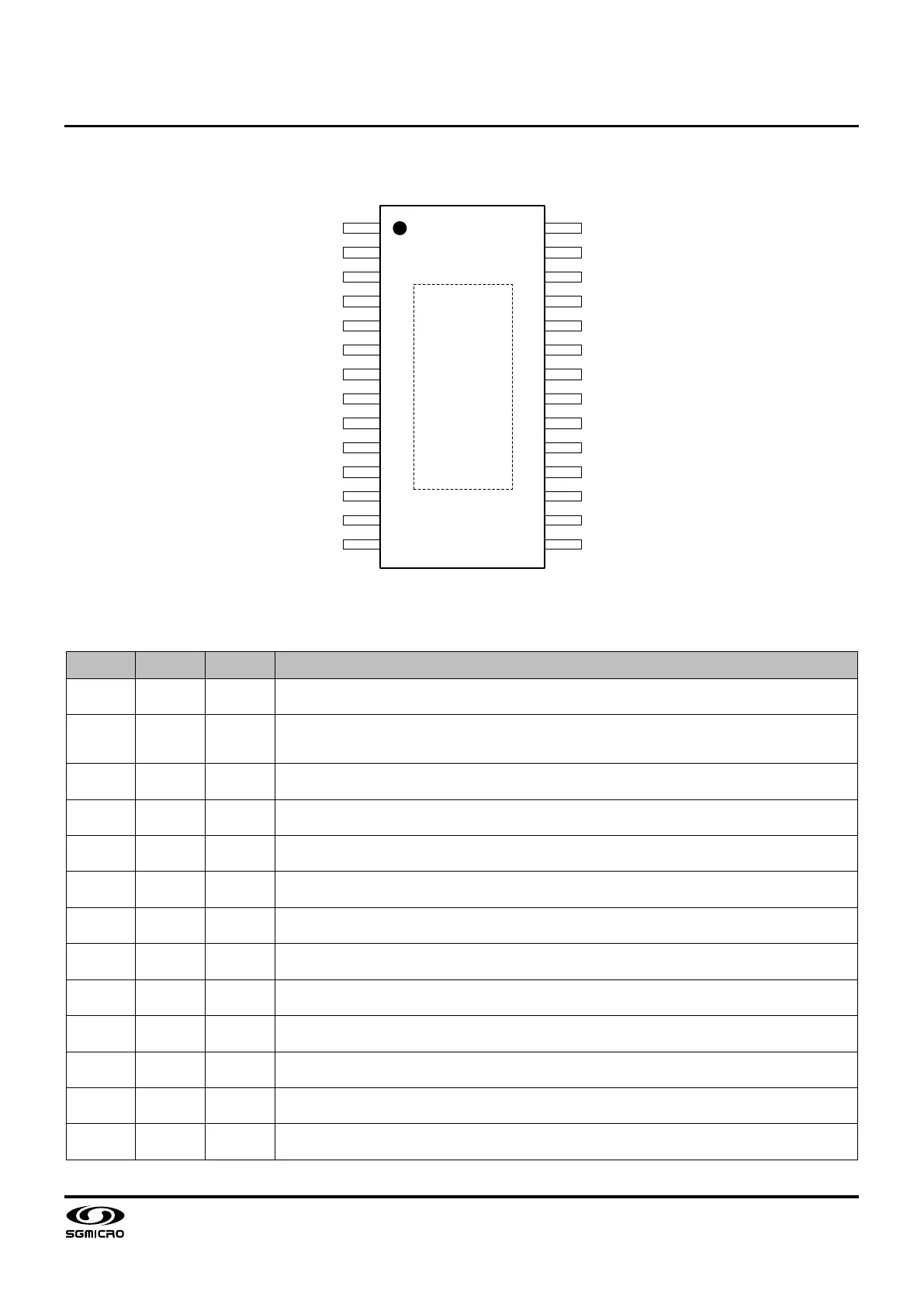
PIN CONFIGURATION
28
1
Exposed
Pad
2
3
4
5
6
7
8
9
10
11
12
13
14
27
26
25
24
23
22
21
20
19
18
17
16
15
EN
FAULTB
INPL
INNL
GAIN
FREQ
AVDD
AGND
GVDD
PLIMIT
INNR
INPR
ALC
MODS
PVDD
PVDD
BSTPL
VOPL
PGND
VONL
BSTNL
BSTNR
VONR
PGND
VOPR
BSTPR
PVDD
PVDD
TSSOP-28 (Exposed Pad)
PIN DESCRIPTION
PIN NAME TYPE DESCRIPTION
1 EN DI
Chip enable (active high) with an on-chip 250kΩ pull-down resistor to ground. A TTL logic
input in compliance with AVDD.
2 FAULTB DO
Open-drain output indicating operational faults of OCP or DCP. Both faults can be set for
auto-
recovery by externally connecting FAULTB to EN. Otherwise, both OCP and DCP faults
must be reset by cycling EN.
3 INPL AI Left-channel non-inverting audio input biased at one half of GVDD.
4 INNL AI Left-channel inverting audio input biased at one half of GVDD.
5 GAIN AO
Voltage gain select with an on-chip 250kΩ pull-down resistor to ground. Connect to a resistor
to ground to set the voltage gain of the audio amplifiers.
6 FREQ AO
PWM frequency select with an on-chip 250kΩ pull-down resistor to ground. Connect to a
resistor to ground to set the PWM frequency with optional spread-spectrum.
7 AVDD P
Analog supply. Connect to a 1µF capacitor for decoupling. Also, add a decoupling resistor of
10Ω between this pin and the system power supply for high-frequency filtering.
8 AGND G Analog ground. Connect to the system power ground GND.
9 GVDD AO Internally generated reference voltage at 5.6V. Connect to a 1µF capacitor for decoupling.
10 PLIMIT AI
Adjustable power limit. Connect to a resistor divider from GVDD to AGND to set the output
voltage limit. Add a 0.1μF capacitor for decoupling.
11 INNR AI
Right-channel inverting audio input biased at one half of GVDD. Connect to ground (without
decoupling capacitor) for mono mode in PBTL configuration.
12 INPR AI
Right-channel non-
inverting audio input biased at one half of GVDD. Connect to ground
(without decoupling capacitor) for mono mode in PBTL configuration.
13 ALC AO
ALC mode select with an on-chip 250kΩ pull-down resistor to ground. Connect to a resistor to
ground or leave open to set ALC dynamic characteristic.