Table of contents Page
1 Object 2
2 Field of application 2
2.1 Interstitial space requirements 2
2.2 Material to be conveyed 2
2.3 Resistance / materials 2
2.4 Double-walled pipes with up to 5 or 25 bar pressure on the inner pipe 4
3 Functional description 5
3.1 Normal operation 5
3.2 Air leak 5
3.3 Liquid leak 5
3.4 Switching values of the leak detector 6
3.5 Description of the display and operating elements 6
4 Mounting instructions 8
4.1 General notes 8
4.2 Mounting the leak detector 8
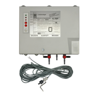
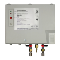
4.3 Mounting the (pneumatic) connection lines 8
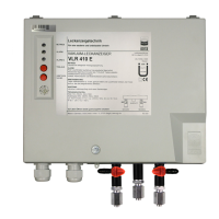
4.4 Mounting the probe (VLR ../E only) 10
4.5 Mounting the solenoid valve(s) (VLR ../E only) 10
4.6 Selection of the (electrical) supply line (VLR ../E only) 11
4.7 Electrical connection 11
4.8 Installation examples 12
5 Start-up 13
6 Operating instructions 13
6.1 General instructions 13
6.2 Intended use 14
6.3 Maintenance 14
6.4 Functional test 14
6.5 Alarm 17
7 Marking 17
8 Index used 18
Drawings:
Position of three-way valves P – 060 000
Installation examples (basic sketches) for pipes P–01 bis Q–04
Block diagram VLR .. SL – 853 600
Block diagram VLR ../E SL – 854 800
Testing equipment P – 115 392
Appendices:
E Usage limits VLR .. E-1
DP Tightness test DP-1
TD Technical data TD-1
ZD Additional pressure switch ZD-1