40
13VT-L200
ADJUSTMENT OF THE VCR ELECTRICAL CIRCUITRY
Notes:
» Before the adjustment:
Electrical adjustments described here are often required after replacement of electronic components and mechanical
parts such as video heads.
Check that the mechanism and all electric components are in good working condition prior to the adjustments,
otherwise adjustments can not be completed.
» Instruments required:
Dual-trace oscilloscope Color bar generator
Blank video cassette tape DC voltmeter
Screwdriver for adjustment Alignment tape (VROATSV), (VRONBZGS)
» Adjustment of the VCR should be done in the TV/VCR combinated style. But there is a function to cut off the high
voltage of TV. Namely, you can check only VCR part by taking the wire lead RC off . Therefore you can use function
on the occasion of checking and adjusting VCR part.
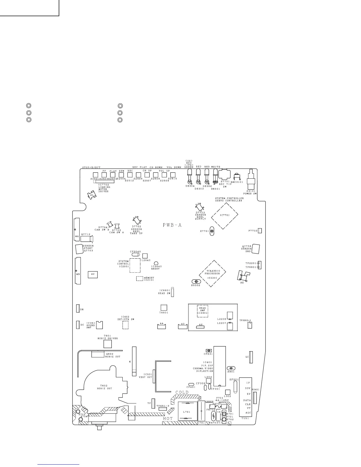
Figure 2-1.
Ë Test points layout of Main Unit.