ADJUSTMENT PRECAUTIONS
This model’s setting are adjusted in two different ways: through the I
2
C bus control and in the conventional
analog manner. The adjustments via the I
2
C bus control include preset-only items and variable data.
1. Setting the service mode by the microprocessor.
1. Short TP1001 & TP1002 to switch to the service mode position, and the microprocessor is in input
mode. (Adjustment through the I2C bus control).
2. Press the CH DOWN / UP key on the remote controller to get ready to select the mode one by one.
3. Press the CH DOWN / UP key on the remote controller to select the modes reversibly one by one.
4. Using the VOLUME UP/ DOWN key on the remote controller, the data can be modified.
5. Disconnect TP1001 & TP1002 to switch to the normal mode (OFF) position, and the microprocessor
is in out of the service mode.
2. Factory Presetting.
1. Short TP1001 & TP1002 to switch to the service mode position and turn on the main power switch.
Initial values are automatically preset, only when a new EEPROM is used (Judge with the first 4 bytes).
2. The initial data are preset as listed in page 6 & 7.
3. Make sure the data need modify or not (Initial data).
Note: Once the chassis has been assembly together and ready to be POWER ON for the FIRST TIME,
make sure to short TP1001 & TP1002 to switch to the service mode position first and then turn on
the main power switch (See 2-(1) above).
Precaution: If haven’t done this initiation, it may possibly generate excessive Beam current.
3. For reference please check with memory map
(UAF-C Series type RH-IX3410CEN5, RH-IX3412CEN5 Attachment)
4. Trouble indications
If the set is interrupted by IIC bus line error, the following indicators work to identify a spot in trouble.
LED (RED) flashing: Flashing time Part's Ref.No. Remarks
2 IC1003 EEP ROM
3 IC801 TVPROCESSOR
4 IC401 AV SWITCH
5 IC305 SOUND PROCESSOR
6 IC2300 (NICAM/IGR) DECODER
8 TU201 TUNER
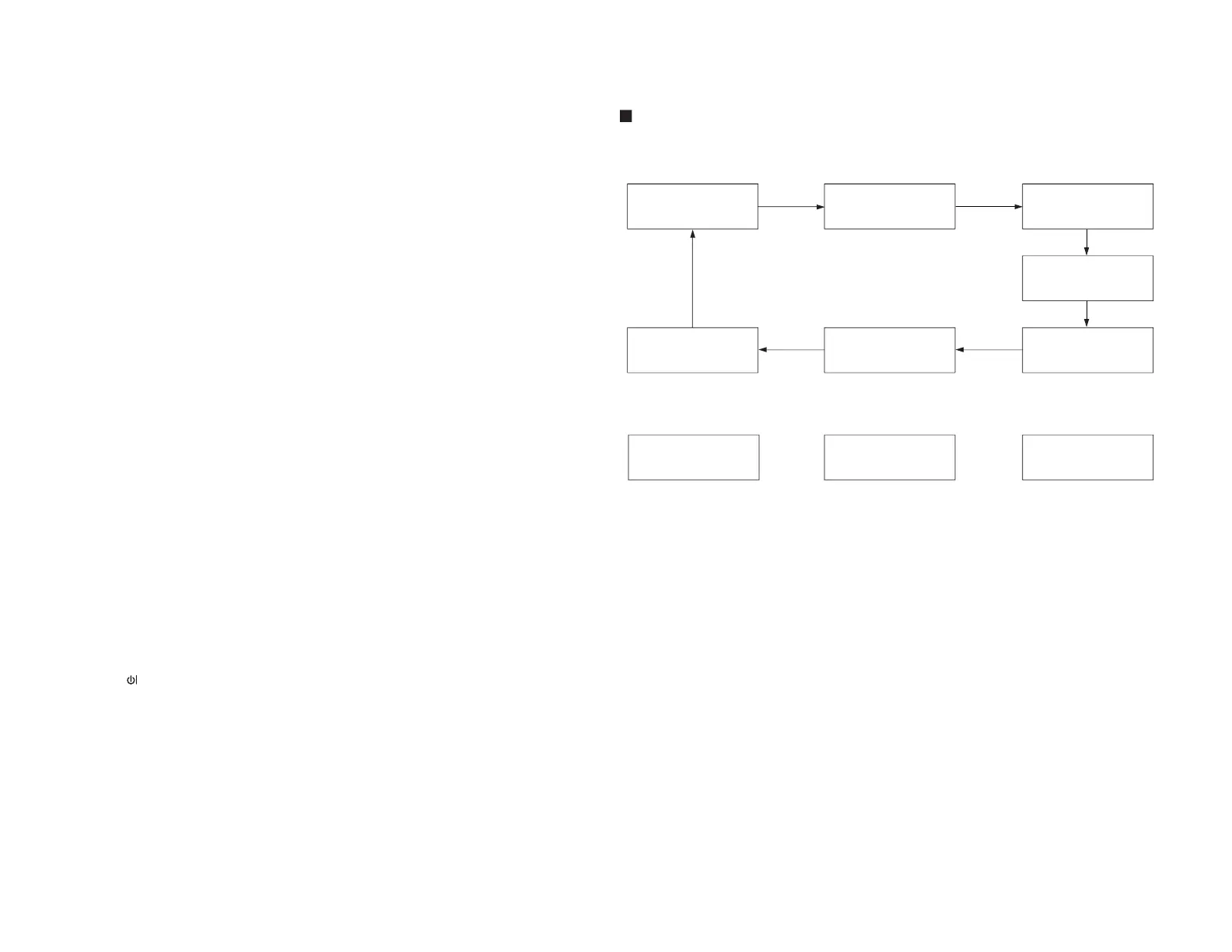
AGC &
GEOMETRIC
MODE
↓
↓
↓
↓
↓
↓
↓
↓
↓
↓
↓
↓
↓
AGC Take Over Point (AGC)
Vertical Slope (V-LIN)
Vertical Amplitude(V-AMP)
Vertical Shift (V-CENT)
Horizontal shift (H-CENT)
East-West width (H-SIZE)
Horizontal Parallelogram (EW//)
East-west Parabola/Width (PARA)
East-west Upper Corner Parabola (COR(U))
East-west Lower Corner Parabola (COR(L))
East-west Trapezium (TRAPE)
Horizontal Bow (HB)
S-Correction (S-COR)
WHITE POINT
ADJ.
MODE
↓
↓
↓
↓
↓
↓
↓
↓
↓
White point Red Standard white temp.(DRI-RS)
White point Green Standard white temp. (DRI-GS)
White point Blue Standard white temp (DRI-BS)
White point Red Cold white temp. (DRI-RC)
White point Green Cold white temp. (DRI-GC)
White point Blue Cold white temp. (DRI-BC)
White point Red Warm white temp. (DRI-RW)
White point Green Warm white temp. (DRI-GW)
White point Blue Warm white temp. (DRI-BW)
SUB
ADJ.
MODE
↓
↓
↓
↓
↓
↓
↓
↓
↓
↓
↓
↓
↓
Max Volume (SUB-VOL)
Sub Contrast (SUB-CON)
Sub Colour (SUB-COL)
Sub Brightness (SUB-BRI)
Sub Tint (SUB-TINT)
Sub Sharpness (SUB-SHP)
Max Hotel Volume (HTL-VOL)
Hotel Program number (HTL-PRG)
Blue Back Contorast (BB-CON)
OSD RGB Reference (RGB)
Black Level off-set R (CUT-R)
Black Level off-set G (CUT-G)
Cathode Drive Level (CDL)
FORWARD : CH DOWN KEY
REVERSE : CH UP KEY
* ( ) means OSD display.
FORWARD : CH DOWN KEY
REVERSE : CH UP KEY
* ( ) means OSD display.
AGC &
GEOMETRIC
MODE
WHITE POINT
ADJ.
MODE
SUB
ADJ.
MODE
Y-DELAY
ADJ.
MODE
MISC.
OPTION
MODE
IC
OPTION
MODE
OFFSET
ADJ.
MODE