27
21KF-80S
Service precaution:
The area enclosed by this line is directly ( )
connected with AC mains voltage.
When servicing the area, connect an insulating
transformer between TV receiver and AC line to
eliminate hazard of electric shock.
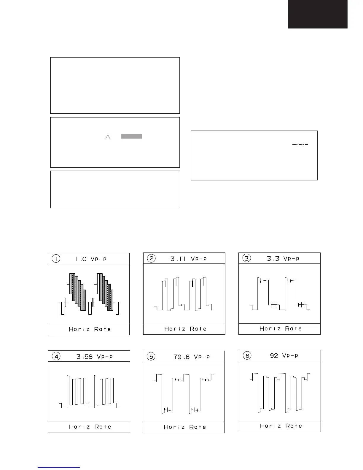
Waveform measurement condition:
Colour bar generator signal of 70 dB from RF input.
1. The unit of resistance «ohm»is omitted (K=1000 ohms.
M= Megaohm).
2. All resistors are 1/16 watt. unless otherwise noted.
3. All capacitors are µF, unless otherwise noted (P= µµF).
4. The capacitor with Part No. RC-FZ9XXXBMNJ is de-
signed to with stand 63V.
5. The capacitor with Part No. RC-FZ4XXXBMNJ is de-
signed to with stand 50V.
Note:
CAUTION
This circuit diagram is original one, therefore
there may be slight difference from yours.
Important safety note:
Parts marked with « » ( ) are important
for maintaining the safety of the set. Be sure to re-
place these parts with specified ones for maintain-
ing the safety and performance of the set.
!
Safety note:
1. Disconnect the AC plug from the AC outlet be-
fore replacing parts.
2. Semiconductor heat sinks should be regarded
as potential shock hazards when the chassis is
operating.
SCHEMATIC DIAGRAMS
Description
Waveforms