21S-FX10F/10S/10N/10U
3 – 13
3. HORIZONTAL, VERTICAL, DEFLECTION LOOP ADJUSTMENT
NO ADJUSTMENT POINT WAVEFORM OR OTHERS
1
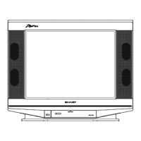
V-SLOPE
(I2C BUS CONTROL)
ADJUSTMENT CONDITION / PROCEDURE
(1) Receive Monoscope Pattern Signal
(PAL 50 Hz).
(2) Choose the service data 02 V-SLOPE.
(3) Adjust the V-SLOPE as shown in Figure 1.1
CAUTION:- PLEASE AGING TV MORE THAN
10 MINUTES BEFORE ADJUSTMENT.
2
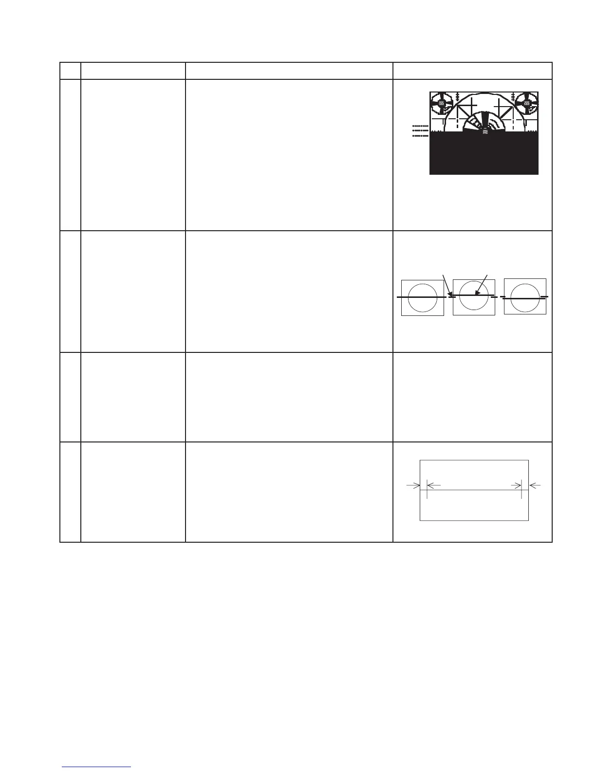
V-SHIFT50
(I2C BUS CONTROL)
(1) Receive Monoscope Pattern Signal
(PAL 50 Hz).
(2) Choose the service data 03 V-SHI-50
(3) Adjust V-SHI-50 bus data to have a most
acceptable vertical position, the monoscope
pattern should be Balance in vertical position.
Note: B line (Monoscope middle line) must
same or nearest higher position to the A
mark (Tube middle mark),refer to the attach
drawing.
Figure 1.1
Figure:
3
V-AMP-50
(12C BUS CONTROL)
(to be done
V-shift adj)
(1) Receive Monoscope Pattern Signal
(PAL 50 Hz).
(2) Choose the service data 04 V-AMP-50.
(3) Adjust V-AMP-50 bus data until the overscan
become 10 ± 1.5 %.
Caution 1: Pls aging TV more than
10 minutes before adjustment
4
H-SHIFT-50
(I2C BUS CONTROL)
(1) Receive Monoscope Pattern Signal
(PAL 50 Hz).
(2) Choose the service data 05 H-SHI-50.
(3) Adjust the H-SHI-50 bus data to have a
balance position to spec of A=B
(as attach drawing).
(4) If cannot make it to A=B, adjust from the
best point so that B slightly smaller than A.
A = Out of spec
B=OK
C = Out of spec
A
B
C
A
OK OK NG
B
AB