21S-FX10F/10S/10N/10U
3 – 14
NO ADJUSTMENT POINT WAVEFORM OR OTHERS
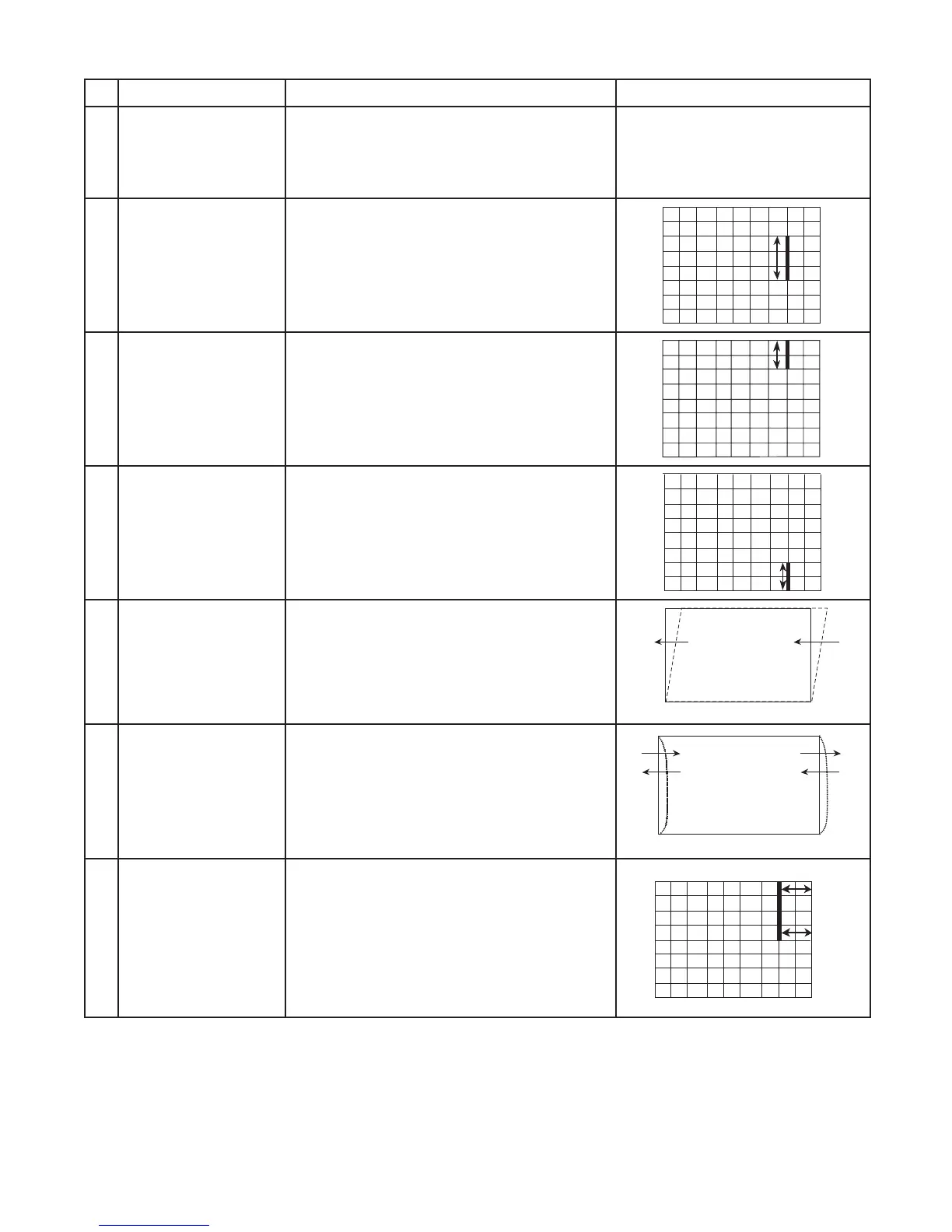
5
EW-W-50
(I2C BUS CONTROL)
ADJUSTMENT CONDITION / PROCEDURE
(1) Receive Monoscope Pattern Signal
(PAL 50 Hz).
(2) Choose the service data 06 EW-W-50.
(3) Adjust EW-W-50 bus data until the overscan
becomes 10 ± 1.5 %.
6
E/W-PAR-50
(I2C BUS CONTROL)
(1) Receive CrossHatch Pattern Signal
(PAL 50 Hz).
(2) Choose the service data 07 E/W-PAR-50.
(3) Adjust the 2nd vertical line from the right
end of the crosshatch pattern so that the
middle 4 blocks are straight.
7
UPCOR-PAR
(I2C BUS CONTROL)
(1) Receive CrossHatch Pattern Signal
(PAL 50 Hz).
(2) Choose the service data 10 UPCOR-PAR.
(3) Adjust the 2nd upper vertical line from the
right end of the crosshatch pattern so that the
upper line are straight.
8
LOCOR-PAR
(I2C BUS CONTROL)
(1) Receive CrossHatch Pattern Signal
(PAL 50 Hz).
(2) Choose the service data 11 LOCOR-PAR.
(3) Adjust the 2nd lower vertical line from the right
end of the crosshatch pattern so that the
bottom line are straight.
9
H-BOW
(I2C BUS CONTROL)
(1) Receive CrossHatch Pattern Signal
(PAL 50 Hz).
(2) Choose the service data 9 H-BOW.
(3) Adjust the 2nd vertical line from the end of the
crosshatch pattern until line is straight
(4) Please refer Figure 9.1
10
H-PAR
(I2C BUS CONTROL)
(1) Receive CrossHatch Pattern Signal
(PAL 50 Hz).
(2) Choose the service data 8 H-PAR.
(3) Adjust the 2nd vertical line from the end of the
crosshatch pattern line is straight
(4) Please refer Figure 10.1
11
EW-TRAP
(I2C BUS CONTROL)
(1) Receive CrossHatch Pattern Signal
(PAL 50 Hz).
(2) Choose the service data 12 EW-TRAP.
(3) Adjust the 2nd vertical line from the right
end of the crosshatch pattern so that the
D1 (center area of the second vertical
line - edge of screen) and D2 (top area of
the second vertical line - edge of screen)
are same.
H-PAR
Figure 9.1
Figure 10.1
H-BOW
D2
D1