EasyManua.ls Logo

Sharp 21V-FS700S User Manual

Sharp 21V-FS700S
91 pages
To Next Page IconTo Next Page
Page #1 background imageLoading...
Page #1 background image
CHAPTER 1. SPECIFICATIONS
[1] SPECIFICATIONS......................................
1-1
CHAPTER 2. IMPORTANT SERVICE NOTES
[1] IMPORTANT SERVICE NOTES ................
2-1
CHAPTER 3. ADJUSTMENT PRECAUTIONS
[1] ADJUSTMENT PRECAUTIONS ................
3-1
[2] ADJUSTMENT ...........................................
3-13
CHAPTER 5. TROUBLE SHOOTING FLOWCHART
[1] TROUBLE SHOOTING FLOWCHART ......
5-1
CHAPTER 6. SOLID STATE DEVICE BASE DIAGRAM
[1] SOLID STATE DEVICE BASE DIAGRAM..
6-1
CHAPTER 7. CHASSIS LAYOUT
[1] CHASSIS LAYOUT ....................................
7-1
CHAPTER 8. BLOCK DIAGRAM
[1] BLOCK DIAGRAM : MAIN UNIT............... 8-1
[2] BLOCK DIAGRAM : CRT UNIT............... 8-3
CHAPTER 9. DESCRIPTION OF SCHEMATIC DIA-
GRAM
[1] DESCRIPTION OF SCHEMATIC DIA-
GRAM...................................................... 9-1
CHAPTER 10. WAVEFORMS
[1] WAVEFORMS....................................... 10-1
CHAPTER 11. SCHEMATIC DIAGRAM
[1] SCHEMATIC DIAGRAM : CRT UNIT..... 11-1
[2] SCHEMATIC DIAGRAM : MAIN UNIT.... 11-2
CHAPTER 12. PRINTED WIRING BOARD ASSEM-
BLIES
[1] PWB-A : MAIN UNIT............................... 12-1
[2] PWB-B : CRT UNIT................................ 12-3
Parts Guide
SERVICE MANUAL
xxxxxxxxx
TopPage
21V-FS700S
No. S6810121VFS700S
COLOUR TELEVISION
Chassis No.GA-7S
MODEL
Auto Fine Tuning
High Contrast Picture (Black Stretch
Circuit)
Stereo
Multi Languages OSD
(English/Spanish)
5 Band Graphic Equalizer
Front AV IN & Rear AV IN / OUT
Terminals
AV Mode (3 Mode)
FEATURES
NTSC
Frequency Synthesizer Tuner
Full Auto System
100-CH Program Memory
CATV (Hyper Band Ready)
Hotel Mode
White Temperature Select
Off Timer
Blue Back Function
Aperture Control Circuit
Child Lock
Component In
AVL Function
Bass+
M.P-In Jack
Picture Noise Reduction Function
Closed Caption
Surround
EZ Setup
In the interests of user-safety (Required by safety regulations in some countries) the set should be restored to its original condition and
only parts identical to those specified should be used.
CONTENTS
The chassis in this receiver is partially hot. Use an isolation transformer between the line cord plug and power receptacle, when servicing
this chassis. To prevent electric shock, do not remove cover. No user-serviceable parts inside. Refer servicing to qualified service personnel.
WARNING
21V-FS700S
CHAPTER 4. MEMORY MAP
[1] MEMORY MAP.............................................4-1

Questions and Answers:

Sharp 21V-FS700S Specifications

General IconGeneral
Screen Size21 inches
TypeCRT
Aspect Ratio4:3
Power SourceAC 110-240V, 50/60Hz
InputsRF, AV, S-Video

Summary

Chapter 1 Specifications

Chapter 1 Specifications

Lists detailed technical parameters like convergence, frequencies, power, dimensions.

Chapter 2 Important Service Notes

Chapter 2 Important Service Notes

Crucial safety and handling guidelines for servicing.

Chapter 3 Adjustment Precautions

Chapter 3 Adjustment Precautions

Precautions and methods for performing adjustments.

Chapter 4 Memory Map

Chapter 4 Memory Map

Maps EEPROM addresses and their data for configuration.

Chapter 5 Troubleshooting Flowchart

Chapter 5 Troubleshooting Flowchart

Step-by-step guide for diagnosing and resolving common issues.

Chapter 6 Solid State Device Base Diagram

Chapter 6 Solid State Device Base Diagram

Visual diagrams of component pinouts and layouts.

Chapter 7 Chassis Layout

Chapter 7 Chassis Layout

Diagram showing the physical placement of components on the chassis.

Chapter 8 Block Diagram

Chapter 8 Block Diagram: Main Unit

High-level functional blocks of the main unit.

Chapter 8 Block Diagram: CRT Unit

Functional blocks of the CRT unit.

Chapter 9 Description of Schematic Diagram

Chapter 9 Description of Schematic Diagram

Explanations of schematic symbols and measurement conditions.

Chapter 10 Waveforms

Chapter 10 Waveforms

Illustrates expected signal waveforms at various test points.

Chapter 11 Schematic Diagram

Chapter 11 Schematic Diagram: CRT Unit

Detailed circuit schematic for the CRT unit.

Chapter 11 Schematic Diagram: Main Unit

Detailed circuit schematic for the main unit.

Chapter 12 Printed Wiring Board Assemblies

Chapter 12 PWB-A: Main Part Side

Printed wiring board layout for the main unit (part side).

Chapter 12 PWB-A: Main Chip Side

Printed wiring board layout for the main unit (chip side).

Chapter 12 PWB-B: CRT Part Side

Printed wiring board layout for the CRT unit.

Sharp Parts Guide

Sharp Parts Guide: Picture Tube

Lists parts related to the picture tube.

Sharp Parts Guide: Printed Wiring Board Assemblies

Lists parts for the printed wiring boards.

Sharp Parts Guide: Main Unit

Lists parts for the main unit.

Sharp Parts Guide: CRT Unit

Lists parts for the CRT unit.

Sharp Parts Guide: Miscellaneous Parts

Lists various other components and parts.

Sharp Parts Guide: Supplied Accessories

Lists items included with the product.

Sharp Parts Guide: Cabinet Parts

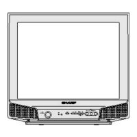
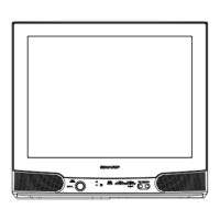
Lists parts related to the television's casing and exterior.

Sharp Parts Guide: Packing Parts

Lists parts related to product packaging and shipping.

Related product manuals