AE-X15PU
2 – 7
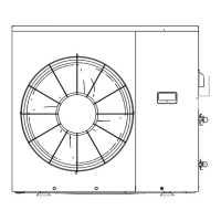
2. Outline of PAM circuit
2.1. PAM (Pulse Amplitude Modulation)
The PAM circuit varies the compressor drive voltage and controls the rotation speed of the compressor.
The IGBT shown in the block diagram charges the energy (electromotive force) generated by the reactor to the electrolytic capacitor for the inverter
by turning ON and OFF.
When the IGBT is ON, an electric current flows to the IGBT via
the reactor (L1) and diode bridge (DB2).
When the IGBT turns OFF, the energy stored while the IGBT
was ON is charged to the voltage capacitor via the diode
bridge (DB1).
As such, by varying the ON/OFF duty of the IGBT, the output
voltage is varied.
208 or
230V
1.9. AUTOMATIC AIR CONDITIONING
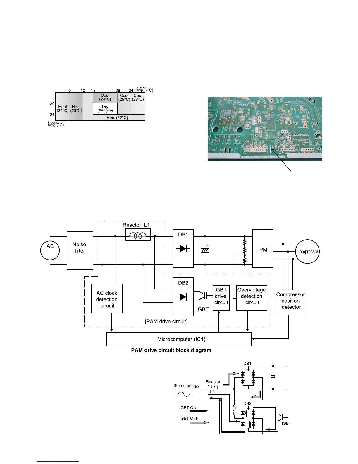
In the AUTO mode, the unit will automatically select COOL or HEAT
mode by comparing the room temperature and your desired tempera-
ture.
The unit will automatically switch between HEAT and COOL mode to
keep the desired temperature.
COANDA and MULTI SPACE button will be inactivated during AUTO
mode.
During operation, if the outdoor temperature changes, the temperature
settings will automatically slide as shown in the chart.
Modes and Temperature Settings
the figures in ( ) are temperature settings
1.10. INACTIVATE 5°F(-15°C) AUTO STOP FUNCTION
During the heating operation, the unit will automatically stop when
the outdoor temperature drops below 5°F(-15°C) to prevent the
outdoor unit from the damage caused by the freezing of the drained
water. The unit will stop its operation for 4 hour and then resume
the operation when the outdoor temperature rises above 7°F(-13.9°C).
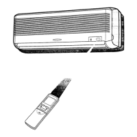
If the customer do not want to use this function, this function can be
inactivated by cutting JPA on outdoor PWB.
1. Power off.
2. Cut the JPA
cut JPA