AYXPC18LR
5 – 6
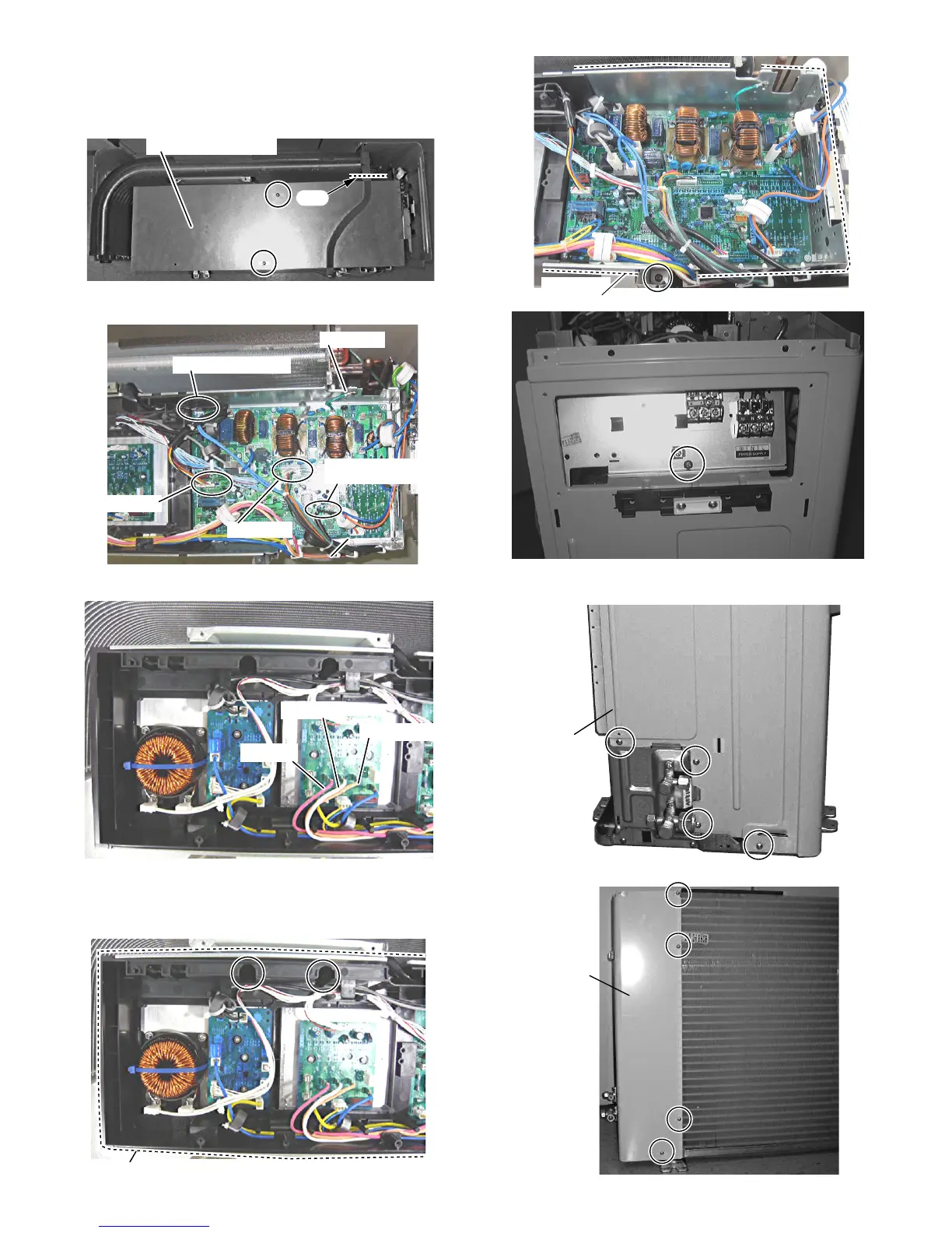
7. Cut the insulators.
8. Remove the 2 screws fixing the control box cover, then remove it.
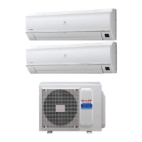
CAUTION: Discharge electrytic capacitor before touching this capaci-
tor or other components or wirings.
9. Disconnect the 4 connectors and the 3 terminals.
Fan motor / Expansion valve / Thermistor
NOTE: Caution to the position of connectors when reinstalling.
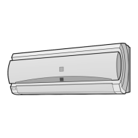
10.Remove the 5 screws fixing the controlbox assembly, then remove
it.
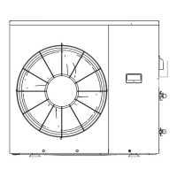
11. Remove the 11 screws fixing the side cover R and slide the side
cabinet R.
Fan motor
Thermistor
Coil of reverse valve
Coil of expansion
valve
Thermistor
Red (U)
White (V)
Orange (W)
Control box
assembly