AYXP26FRN
3 – 9
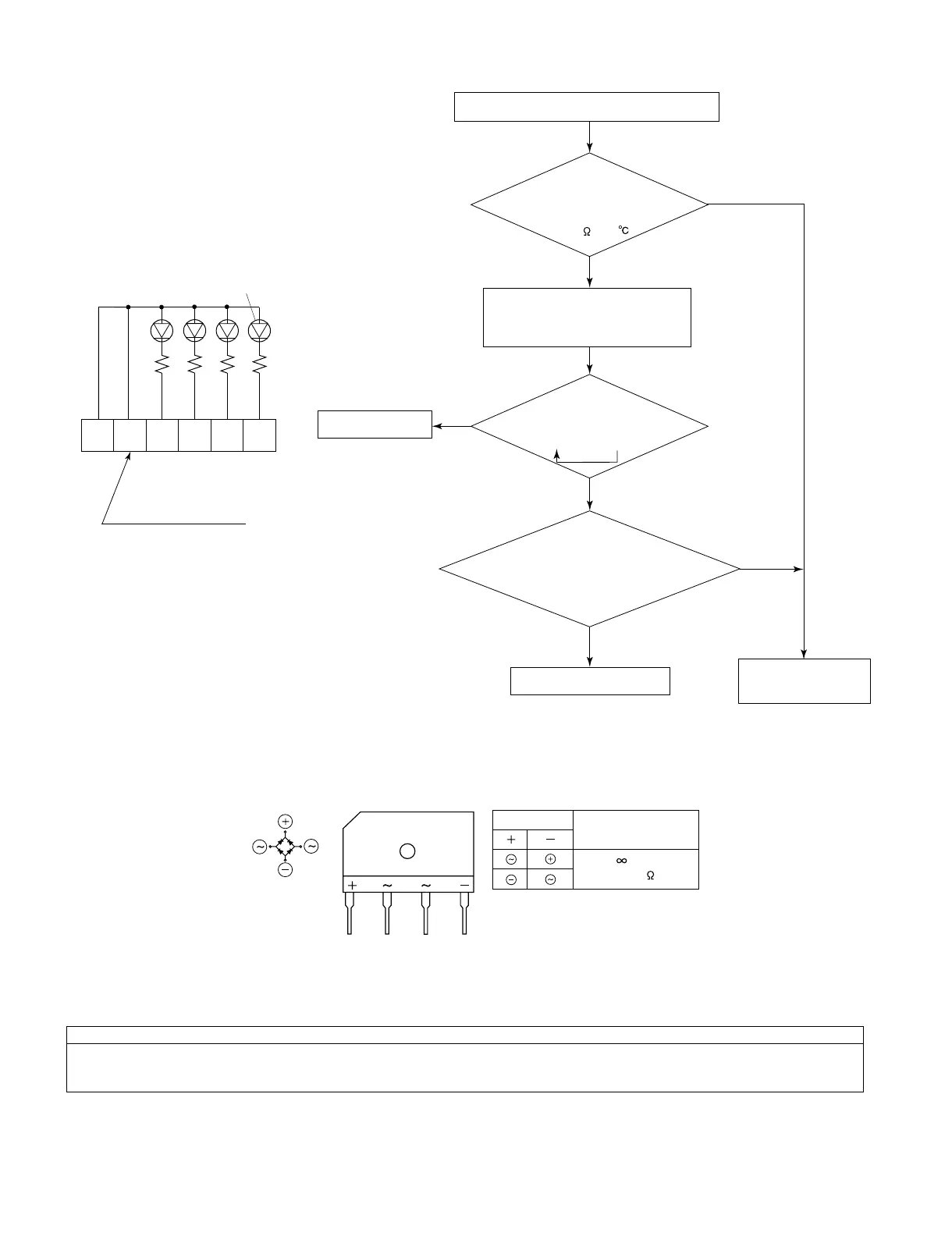
2. Procedure for determining defective expansion valve
3. Diode bridge check method
Turn off the power and let the inverter electrolytic capacitor (C9, C10) discharge completely. Then use a tester and check continuity.
When using a digital tester, the (+) and (-) tester lead wires in the table must be reversed.
4. Inverter electrolytic capacitor (C9, C10) check method
Turn off the power, let the inverter electrolytic capacitor (C9, C10) discharge completely, and remove the capacitor from the control printed circuit
board (PWB). First, check the case for cracks, deformation and other damages. Then, using a needle-type tester, check continuity.
Determination of normal condition
The tester needle should move on the scale and slowly returns to the original position. The tester needle should move in the same way when
polarities are reversed. (When measurement is taken with the polarities reversed, the tester needle exceeds the scale range. Therefore, let the
capacitor discharge before measurement.)
Measure resistance in expansion valve coil.
Normal resistance between red
terminal of expansion valve
lead wire and each terminal:
about 46 (at 20 )
Insert checker shown at left into
connector (CN12) on control PWB, and
operate air conditioner.
If frost accumulates on 2-way valve after 10 to 20
minutes of cooling operation, then thermistors with
yellow and black lead wires may be defective. Check
these thermistors.
Replace thermistor assembly.
Replace control PWB.
Replace expansion
valve assembly.
NO
NO
YES
YES
Defective thermistor
Thermistors in
normal condition
Checker
LED
(red)
Connector
J.S.T. XAP-06V-1
Terminal
SXA-001T-P0.6
4
32
1
5
6
5.6K
5.6K
5.6K
5.6K
Do LEDs on checker light in orderly
sequence
(lighting of 1 LED => lighting of 2 LEDs)
B
Needle-type tester
Normal resistance value
(several M )
Value in ( ) is for digital tester.