AEX3M18JR
5 – 4
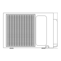
18.Disconnect the 5 terminals (T1, 2, 4, 6, MRY1) and 3 connectors
(CN14, CN2, CN13 (Active Filter)).
19.Remove the 3 screws fixing the power supply board unit (PWB).
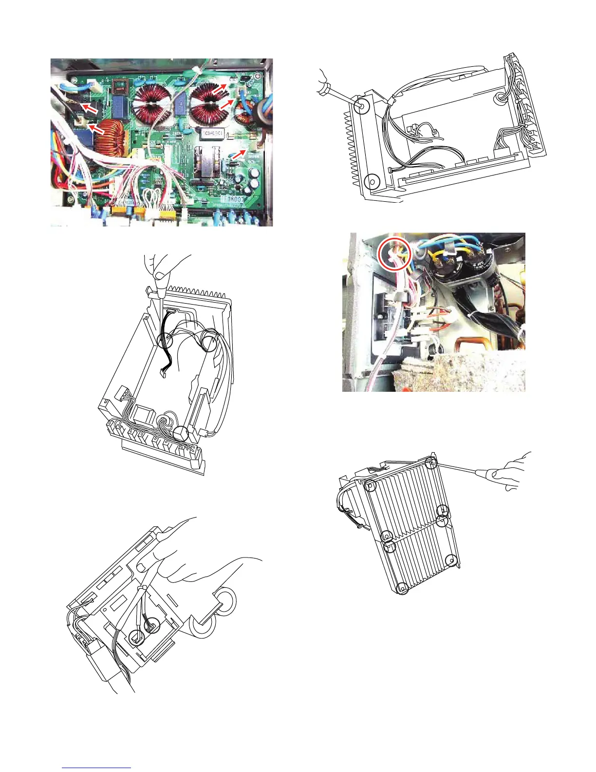
20.Disconnect 2 connectors (CN1,CN9). Then lift up the relay board
unit (PWB) and remove it.
21.Remove the 2 screws fixing the heat sink cover then remove it.
22.Cut a wire fixing board.
23.Remove the each of 4 screws fixing the heat sink.
NOTE: Confirm two kinds of spacer put in 4 holes have clung.
Seal the 4 burring holes with silicone sealer before reinstalling.
24.Disconnect the 5 terminals (TP, TU, TV. TW, TN) and 1 connector
(CN114) on the IPM PWB. And Remove the 2 screws fixing the
IPM PWB and remove it.
NOTE: When the IPM PWB re-install, silicone grease must be paste
to the back face of the IPM.