EasyManua.ls Logo

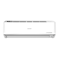
Sharp AH-X108E - User Manual

Sharp AH-X108E
56 pages
To Next Page IconTo Next Page
Loading...
AH/AU-X108E
AY/AE-X108E
AH/AU-X138E
AY/AE-X138E
1
SHARP CORPORATION
Page
SPECIFICATIONS .......................................................................................................................................... 2
EXTERNAL DIMENSIONS............................................................................................................................... 4
WIRING DIAGRAMS....................................................................................................................................... 5
ELECTRICAL PARTS .................................................................................................................................... 10
BLOCK DIAGRAM ......................................................................................................................................... 12
MICROCOMPUTER CONTROL SYSTEM.................................................................................................... 14
FUNCTIONS ................................................................................................................................................. 25
FUNCTION AND OPERATION OF PROTECTIVE PROCEDURES ............................................................. 30
BREAKDOWN DIAGNOSIS PROCEDURE .................................................................................................. 32
REFRIGERATION CYCLE ........................................................................................................................... 34
PERFORMANCE CURVES .......................................................................................................................... 36
DISASSEMBLING PROCEDURE .................................................................................................................. 38
OPTION ......................................................................................................................................................... 45
REPLACEMENT PARTS LIST ....................................................................................................................... 46
TABLE OF CONTENTS
S6831AYX138E/
SERVICE MANUAL
INDOOR UNIT
AH-X108E AY-X108E
AH-X138E AY-X138E
AU-X108E AE-X108E
AU-X138E AE-X138E
OUTDOOR UNIT
In the interests of user-safety (Required by safety regulations in some
countries) the set should be restored to its original condition and only
parts identical to those specified should be used.
MODELS
SPLIT TYPE
ROOM AIR CONDITIONERS
Question and Answer IconNeed help?

Do you have a question about the Sharp AH-X108E and is the answer not in the manual?

Sharp AH-X108E Specifications

General IconGeneral
BrandSharp
ModelAH-X108E
CategoryAir Conditioner
LanguageEnglish

Summary

Specifications

Electrical Data

Details electrical parameters like phase, voltage, current, input, and power factor.

Refrigerant System

Information on refrigerant volume, noise level, and system components.

Fan System

Details on fan drive, airflow quantity, and fan type.

Connections

Information on refrigerant coupling and tube sizes.

Others

Safety device and air filter specifications.

External Dimensions

Indoor Unit Dimensions

Diagrams showing the physical size and measurements of the indoor unit.

Outdoor Unit Dimensions

Diagrams showing the physical size and measurements of the outdoor unit.

Wiring Diagrams

General Indoor Unit Wiring Diagram

Overall wiring schematic showing connections between indoor and outdoor units.

AU-X108 E Wiring Diagram

Detailed wiring schematic for the AU-X108E model.

AU-X138 E Wiring Diagram

Detailed wiring schematic for the AU-X138E model.

AE-X108 E Wiring Diagram

Detailed wiring schematic for the AE-X108E model.

AE-X138 E Wiring Diagram

Detailed wiring schematic for the AE-X138E model.

Electrical Parts

Block Diagrams

Indoor Unit Block Diagram

Functional block diagram illustrating the indoor unit's internal system.

Outdoor Unit Block Diagram

Functional block diagram of the outdoor unit's internal system.

Microcomputer Control System Diagrams

AH-X108 E Control Circuit Diagram

Detailed electronic circuit diagram of the AH-X108E microcomputer control system.

AU-X108 E Control Circuit Diagram

Detailed circuit diagram for the AU-X108E control system.

AH-X138 E Control Circuit Diagram

Detailed circuit diagram for the AH-X138E control system.

AU-X138 E Control Circuit Diagram

Detailed circuit diagram for the AU-X138E control system.

AY-X108 E Control Circuit Diagram

Detailed circuit diagram for the AY-X108E control system.

AE-X108 E Control Circuit Diagram

Detailed circuit diagram for the AE-X108E control system.

AY-X138 E Control Circuit Diagram

Detailed circuit diagram for the AY-X138E control system.

AE-X138 E Control Circuit Diagram

Detailed circuit diagram for the AE-X138E control system.

Printed Wiring Boards

Indoor Unit PWB Layouts

Printed wiring board layout for indoor unit models.

Outdoor Unit PWB Layouts

Printed wiring board layout for outdoor unit models.

Functions

Temperature Adjustment

Details on proportional-integral control, initial control, and temp. adjustment range.

Indoor Fan Control

How the indoor fan is controlled for various conditions.

Prevention Controls

Covers overheating, freezing, cold air prevention, and hot keep function.

Fan Speed and Operating Frequency

Relationship between fan speed, air quantity, frequency, and heat exchanger.

Operation Modes and Timers

Explains automatic operation, timers, swing, restart, and special modes.

Full Power Operation

Immediate cooling/heating at max power.

Preheat and Power ON Start

System preheats compressor; unit starts via jumper wire.

Compressor Relay, Power Selector, and Auto Restart

Operation of compressor relay, power selection, and auto restart.

Defrost Operation Overview

Overview of the defrost cycle during heating.

Protective Procedures

Defrosting Conditions and Control

Conditions that enable defrosting start, during defrost, and defrost stop.

Frequency and Current Protection

Manages frequency based on AC current, overheating, and abnormal conditions.

Compressor and Thermistor Protection

Protects against compressor lock, overheating, and thermistor errors.

Indoor Fan Protection

Covers fan lock, RPM error, freezing, and overheating prevention.

Signal and Valve Error Protection

Protection against serial signal loss and four-way valve errors.

Break Down Diagnosis Procedure

Self-Diagnostic Using LED Indicators

Guide to diagnosing faults using LED indicators and conditions.

Refrigerant Cycle

AH;AH Refrigerant Cycle Diagrams

Diagrams illustrating the refrigerant flow for AH-X108E/AH-X138E.

AY Refrigerant Cycle Diagrams

Diagrams illustrating the refrigerant flow for AY-X108E/AY-X138E.

Standard Refrigerant Conditions

Specifies standard conditions for refrigerant cycle measurements.

Performance Curves

AH-X108 E Cooling Performance Curves

Graphs showing cooling performance based on outside air temperature.

AY-X108 E Cooling Performance Curves

Graphs showing cooling performance based on outside air temperature.

AY-X108 E Heating Performance Curves

Graphs showing heating performance based on outside air temperature.

AH-X138 E Cooling Performance Curves

Graphs showing cooling performance based on outside air temperature.

AY-X138 E Cooling Performance Curves

Graphs showing cooling performance based on outside air temperature.

AY-X138 E Heating Performance Curves

Graphs showing heating performance based on outside air temperature.

Disassembling Procedure (Indoor Unit)

Removing Front Panel and Covers

Steps for removing the front panel, screw covers, and control box cover.

Removing Internal Components

Steps for removing ground wire, protect cover, thermostat, and drain pan.

Removing Evaporator and Fan Assembly

Steps for removing the evaporator, fan motor, and electric control box.

Removing Other Indoor Unit Parts

Steps for removing receiver unit, terminal board, and louver motor.

Servicing Procedure (Outdoor Unit)

Outdoor Unit Cover Removal

Steps for removing control box cover and cabinet panels.

Outdoor Unit Component Removal

Steps for removing control box, thermistors, and fan.

Reactor and Compressor Part Removal

Steps for removing reactor box, reactor, and compressor cover.

Option: Air Purifying Filter

Filter Replacement Procedure

Step-by-step guide for replacing the air purifying filter.

Filter Replacement Intervals Guideline

Recommended intervals for replacing air purifying filters.

Replacement Parts List

AH;AU-X108 E;AH-X138 E Parts

Lists cabinet, control box, cycle, accessory, and screw parts for AH/AU models.

AU-X138 E;AE-X138 E Parts

Lists cabinet, control box, cycle, and screw parts for AU/AE models.

Parts Diagrams

Outdoor Unit AU-X108 E Parts Diagram

Exploded view showing part numbers and assembly of the AU-X108E outdoor unit.

Outdoor Unit AE-X108 E Parts Diagram

Exploded view showing part numbers and assembly of the AE-X108E outdoor unit.

Outdoor Unit AU-X138 E Parts Diagram

Exploded view showing part numbers and assembly of the AU-X138E outdoor unit.

Outdoor Unit AE-X138 E Parts Diagram

Exploded view showing part numbers and assembly of the AE-X138E outdoor unit.

Related product manuals