GB-1
PIPING
Model
Max. piping
length:A
Max. height
difference:B
Min. piping
length
Additional refrigerant
(piping length exceeds 7.5m)
AY-AP9NR
10 m 5 m
1 m 15 g/m
AY-AP12NR
15 m 7 m
• Standard piping length is 5m.
• When the outdoor unit is placed at a higher level than the
indoor unit, provide a trap near the hose’s lead-in port.
Use the refrigerant pipes shown in the table below.
Pipe size Pipe thickness Thermal insulation
Liquid side
1/4" (ø 6.35 mm)
0.8 mm
Thickness: 6 mm or thicker
Material: Polyethylene foam
Gas side
AY-AP9NR
3/8" (ø 9.52 mm)
AY-AP12NR 1/2" (ø 12.7 mm)
• The thermal insulation should cover both the gas and liquid pipes.
A
B
B
ITEMS
Q’ty
ITEMS
Q’ty
ITEMS
Q’ty
ITEMS
Q’ty
1
MOUNTING PLATE
1
3 LONG SCREW
(M4.2 x 25)
To fi x the mounting plate
.
7
6 SPECIAL SCREW
(M4.2 x 16)
To fi x the REMOTE CONTROL.
1
9
DRAIN HOSE ADAPTER
(Included with the outdoor
unit)
1
2 WALL PLUG
To fi x the mounting plate. (7)
To fi x the remote control. (1)
8
4 REMOTE CONTROL
1
7 SHORT SCREW
(M4.2 x 13)
To fi x the CABLE COVER.
1
10
FLARE NUT
1
5 DRY BATTERY
2
8 CABLE COVER
1
11
OPERATION MANUAL
1
12
INSTALLATION MANUAL
1
INSTALLATION DIAGRAM
NOTES ON LOCATIONS
Provide as much installation space as possible for effi cient
air-conditioning.
50 mm or more
50 mm or
more
50 mm or more
300 mm or
more
2000 mm or more
300 mm or more
500 mm or
more
ACCESSORIES
SAFETY PRECAUTIONS
• Installation must be made in accordance with the installation manual by
qualifi ed service personnel.
Incorrect work will cause electric shock, water leak, fi re.
•
Be sure to use the attached accessories parts and specifi ed parts for installation.
Use of other parts will cause electric shock, water leak, fi re, the unit falling.
• The appliance shall be installed in accordance with national wiring regulations.
Wrong connection can cause overheating or fi re.
• After installation has complete, check that there is no leakage of refrigerant
gas.
If the refrigerant gas contact with fi re, it may generate toxic gas.
• Ventilate the room if refrigerant gas leaks during installation.
If the refrigerant gas contact with fi re, it may generate toxic gas.
• Use the specifi ed electrical cable.
Make
sure the cable is secured
in place and that the terminals are free of any
excess force from the
cable. Otherwise overheating
or fi re may result.
• Form the cable so that the control box cover, the cord holder and cable
holder are not loose.
Otherwise overheating, fi re or electric shock may result.
70 mm or more
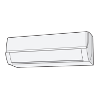
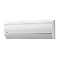
Indoor unit
1. Keep the air outlet clear of any obstacle so that outgoing air fl ows
smoothly in the entire room.
2.
Make a drain hose hole for easy drainage.
3.
Provide suffi cient space on
both sides and above the unit.
4. The air fi lters should be easily taken in and out.
5.
Keep TV set, radio and the like 1 m or more away from the
unit and
the remote control.
6. Keep the air inlet clear of obstacles that could block incoming air.
7.
The remote control may not function properly in a room equipped
with
an electronic simultaneous-start or rapid-start fl uorescent
lighting.
8.
Select a location that does not cause loud operation noise
and ex-
treme vibrations.
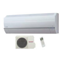
Outdoor unit
1. Place the outdoor unit on a stable base.
2.
Provided
suffi cient space around the unit. It should also be well ventilated.
3.
The unit should not be exposed to strong wind nor splashed with rain
water.
4. Water drain from the unit should be let out without problem.
Lay a drain hose if required.
5.
Keep TV set, radio and the like 1 m or more away from the unit
.
6. Avoid locations exposed to machine oil vapor, salty air (facing the seashore,
for example),
hot spring vapor sulfur gas, etc. Such location can cause
breakdown.
7.
Avoid locations exposed to muddy water (along a road, for example) or
where the unit can be
tampered with.
8.
Select a location where the outgoing air or operating noise cannot annoy
others.
9. Keep the air outlet opening free of any obstacle. This could affect the performance of the unit
and create loud noises.
Trap
• Tighten the fl are nut with a torque wrench according to the specifi ed method.
If the fl are nut is tightened too hard, the fl are nut may be broken after a long time
and cause refrigerant gas leakage.
• When installing the unit, take care not to enter air substance other than the
specifi ed refrigerant(R410A) in the refrigerant cycle.
Otherwise, it will cause burst and injury as a result of abnormal high pressure in the
refrigerant cycle.
• Be sure to connect the refrigerant pipe before running the compressor.
Otherwise, it will cause burst and injury as a result of abnormal high pressure in the
refrigerant cycle.
• Earth the unit.
Incomplete earth may cause electrical shock.
• Install an earth leakage breaker to avoid electric shock in case of leak.
Use the current-activated, high-sensitivity, high-speed type breaker with a rated
sensitivity current of below 30 mA and an operating time of below 0.1 second.
• Arrange the drain hose to ensure smooth drainage.
Insuffi cient drainage may cause wetting of the room, furniture etc.
• This room air conditioner uses refrigerant R410A.
Use the pipe, fl are nut and tools exclusively for R410A.
Carefully read and follow these instructions for smooth and trouble-free installation.
INSTALLATION DIMENSION OF INDOOR UNIT
860
108
A
125
J
175
115
I
F
E
D
J
E
A
F
I
D
292
45
30
Length unit: mm
Center of wall hole
Center of
wall hole
Outline of
indoor unit
(Unit size)
(Unit size)
Coating tape
(Commercially available)
Gas pipe end
Liquid pipe end
ENGLISH
500 mm or more
04_A3AYAP9_2NR.indb GB-104_A3AYAP9_2NR.indb GB-1 2012-01-12 20:44:552012-01-12 20:44:55