Do you have a question about the Sharp CD-C401E and is the answer not in the manual?
First part of the electronic circuit diagram for CD-C401E/CP-C401E.
Second part of the electronic circuit diagram for CD-C401E/CP-C401E.
Third part of the electronic circuit diagram for CD-C401E/CP-C401E.
Fourth part of the electronic circuit diagram for CD-C401E/CP-C401E.
Fifth part of the electronic circuit diagram for CD-C401E/CP-C401E.
Sixth part of the electronic circuit diagram for CD-C401E/CP-C401E.
Seventh part of the electronic circuit diagram for CD-C401E/CP-C401E.
Eighth part of the electronic circuit diagram for CD-C401E/CP-C401E.
Ninth part of the electronic circuit diagram for CD-C401E/CP-C401E.
First part of the wiring diagram for CD-C401E/CP-C401E.
Second part of the wiring diagram for CD-C401E/CP-C401E.
Third part of the wiring diagram for CD-C401E/CP-C401E.
First part of the cabinet exploded view for CD-C401E/CP-C401E.
Second part of the cabinet exploded view for CD-C401E/CP-C401E.
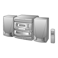
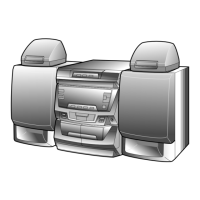
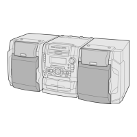
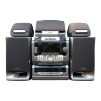
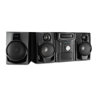
This document is a service manual for the SHARP CD-C401E and CP-C401E models, which together constitute the CD-C401E system. It provides detailed information for servicing these units, noting that they share a similar structure with the former CD-C401H and CP-C402 models, with only differences in certain outer parts being explicitly described. The manual emphasizes user safety, stating that sets should be restored to their original condition using only specified identical parts. It also includes a note for U.K. users regarding copyright and performers' protection acts, advising consultation of relevant statutory enactments.
The manual begins by detailing the differences in components between the CD-C401H/CP-C402 and CD-C401E/CP-C401E models. This includes integrated circuits, transistors, diodes, vibrators, capacitors, resistors, other circuitry parts, CD mechanism parts, cabinet parts, and accessories/packing parts. Each entry lists the reference number, part number for both the old and new models, and a brief description, along with a "★ MARK: SPARE PARTS-DELIVERY SECTION" indicator for parts that are specifically for spare parts delivery.
For integrated circuits, the main system microcomputer, IX0217AW, is identified as RH-iX0217AWZZ for the CD-C401E, replacing the RH-iX0182AWZZ from the CD-C401H. Transistors show a change where the VSKTC3199GR-1 (Digital, NPN, KTC3199 GR) is "Not used" in the new model. Diodes, specifically Silicon, 1SS119 types (VHD1SS119//-1), are also marked as "Not used" in the new model for several reference numbers (D4, 5, D203, 204, D301, 302, D382, D602, 603). Zener diodes, however, are updated: VHEUZ5R1BSB-1 (5.1V, MTZJ5.1B) is replaced by VHEMTZJ5R1B-1, and VHEUZ3R3BSB-1 (3.3V, MTZJ3.3B) is replaced by VHEMTZJ3R3B-1. The vibrator, a crystal operating at 16.93 MHz, changes from RCRM-0008AWZZ to 92LCRSTL1746AT.
Capacitors show several changes. For instance, C37, a 220 µF, 6.3V Electrolytic capacitor (RC-GZA227AF0J), is "Not used" in the new model. C239, a 0.082 µF, 50V Mylar capacitor (RC-QZ0025AWZZ), is replaced by VCQYKA1HM823K. Similarly, C358 (470 pF, 50V) is "Not used," and C394 (120 pF, 50V) and C395 (100 pF, 50V) are replaced by VCKYPA1HB121K and VCKYMN1HB101K, respectively. Many other capacitors, particularly those in the 0.01 µF, 16V range, are updated from 'K' suffix to 'N' suffix part numbers (e.g., VCTYMN1CY103K to VCTYMN1CY103N). Larger electrolytic capacitors like C902 (2200 µF, 50V) and C903 (3300 µF, 35V) are also updated to VCEAZW1HW228M and VCEAZW1EW338M, respectively.
Resistors also have updates, with some being marked as "Not used" in the new model (R94, R355, R356, R398, R400). Others, like R391 (47 kohms, 1/6W), are updated from VRD-ST2CD472J to VRD-ST2CD473J. Jumper resistors (0 ohm, Ø1.4 x 3.5mm, Ivory) for R709, 710, and R713 are updated from VRD-MN2BD103J to VRD-MN2BD000C.
In other circuitry parts, connectors are updated: CNS201 (3 Pin) from QCNWN0919AWZZ to QCNWN0634AWZZ, and CNS202 (7 Pin) from QCNWN0920AWZZ to QCNWN0635AWZZ. The antenna terminal (SO301) changes from QTANC0103AWZZ to QTANC0101AWZZ. For CD mechanism parts, the push-type switch (SW4) for "Pickup In" is updated from QSW-F9001AWZZ to QSW-F9001AW01.
Cabinet parts show extensive changes. The front panel assembly (201) is updated from 92LCAB2450AS1 to 92LCAB2899AS1. The display panel (201-2) remains the same as CD-C401H (HDECQ0248AWSA). The back board (202) is updated from GITAR0245AWSA to GITAR0365AWSA. Side panels (203, 204) and the top cabinet (205) are updated with 'B' suffix part numbers (e.g., GITAS0035AWSA to GITAS0035AWSB). The CD tray cover (206) is also updated from GCVA1148AWSA to GCVA1148AWSB. Many buttons for Tape 1 (Record, Play, Rew, FF, Stop) and Tape 2 (Play, Stop) are updated from 'AWSA' to 'AWSC' suffix part numbers (e.g., JBTN-0106AWSA to JBTN-0106AWSC). Cassette holder assemblies for Tape 1 (248) and Tape 2 (249) are updated from 92LMEC2448CTS1/2 to 92LMEC2899CTS1/2. The panel for cassette Tape 1 (248-2) and Tape 2 (249-2) remain the same as CD-C401H. The tape mechanism assembly (267) is updated from 92LMECHA2448A to 92LMECHA2899A. Various belts (FR Belt, Drive Belt for Tape 1 and Tape 2), the erase head, pinch roller assembly, and record/playback head are updated with new part numbers. The tape motor with pulley (267-7) is updated from RMOTM0004AWM1. Leaf switches for Tape 1 Main, Tape 2 Main, Tape 1 Rec, and Tape 2 Play are also updated.
Accessories and packing parts also reflect changes. The packing case (3) is updated from SPAKC0539AWZZ to SPAKC0676AWSA. The operation manual (6) is updated from TINSE0169AWZZ to TINSE0223AWZZ. The registration card (9) is updated from 92LCARD1751A to TGAN-3170UMZZ. The remote control (11) is updated from RRMCG0103AWSA to RRMCG0150AWSA. The battery lid for the remote control (11-1) remains the same as CD-C401H. The bar code label (12) is updated from "Not used" to TLABE0233AWZZ.
The manual then presents a "DIFFERENCE BETWEEN CP-C402 AND CP-C401E" section specifically for speaker box parts. The net frame assembly (701) is updated from 92L121-0099 to 92L121-0148. The speaker box assembly (702) is updated from 92L051-0034 to 92L051-0061. The duct panel (703) is updated from 92L316-0026 to 92L316-0063. The label for specifications (706) is updated from 92L351-0170 to 92L351-0308. An exploded view of the speaker assembly (Figure 3) is provided, highlighting the woofer (SP1(L-CH), SP2(R-CH)) and showing the locations of parts 701, 702, 703, 704x2, 705, 706, and 707x4. The "CHANGE PARTS" are indicated with a specific symbol.
Following the parts lists, the manual includes a series of schematic diagrams (Figures 4 through 11) for the main PWB-A1 and display PWB-A2, detailing the circuitry for various functions such as the CD servo and amplifier, main signal control, audio processor, power amplifier, FM/AM tuner, and microcomputer control. These schematics use symbols to indicate "Change/Eliminated/Addition PARTS," allowing technicians to quickly identify modifications between the models.
Figure 4, "SCHEMATIC DIAGRAM (1/9)," shows the CD servo and amplifier section, including IC1 (LA9241M SERVO AMP) and the pickup unit. Figure 5, "SCHEMATIC DIAGRAM (2/9)," illustrates the main PWB-A1, focusing on the main signal control with IC2 (LC78623D MAIN SIGNAL CONTROL) and the loading motor driver (IC91 LC78611HS). Figure 6, "SCHEMATIC DIAGRAM (3/9)," covers the audio processor with IC431 (LC75394E AUDIO PROCESSOR). Figure 7, "SCHEMATIC DIAGRAM (4/9)," details the power amplifier with IC601 (LA4282) and voltage regulators (IC922 KIA7812P, IC921 KIA7805P). Figure 8, "SCHEMATIC DIAGRAM (5/9)," shows the playback and record signal paths for Tape 1. Figure 9, "SCHEMATIC DIAGRAM (6/9)," continues with the playback and record/playback amplifier (IC201 AN7345K). Figure 10, "SCHEMATIC DIAGRAM (7/9)," illustrates the FM and AM signal processing. Figure 11, "SCHEMATIC DIAGRAM (8/9)," details the FM IF DET/FM MPX/AM (IC351 LA1805) and PLL (IC381 LC72131) sections. Figure 12, "SCHEMATIC DIAGRAM (9/9)," focuses on the display PWB-A2, including LCD701 and the system microcomputer (IC701 IX0217AW).
Wiring side P.W.Board diagrams (Figures 13, 14, 15) are also provided to guide technicians in locating components and understanding connections. Figure 13, "WIRING SIDE OF P.W.BOARD (1/3)," shows connections for the pickup unit, motor PWB-C, CD motor PWB-B, tape heads, and the power transformer. Figure 14, "WIRING SIDE OF P.W.BOARD (2/3)," illustrates the display PWB-A2. Figure 15, "WIRING SIDE OF P.W.BOARD (3/3)," shows the main PWB-A1.
Finally, the manual includes exploded views of the cabinet (Figures 16 and 17) to aid in disassembly and reassembly. Figure 16, "CABINET EXPLODED (1/2)," shows the overall structure, highlighting the main PWB-A1, PWB-A2, PWB-A3, PWB-A4, LCD701, IC601, IC921, IC922, and the tape mechanism assembly. It notes that only the unit and consumable parts are supplied as spare parts for the tape mechanism. Figure 17, "CABINET EXPLODED (2/2)," provides a detailed view of the CD mechanism components.
The "PACKING OF THE SET" section describes the packaging materials for both the CD-C401E unit and the CP-C401E speakers, including polyethylene bags, packing cases, operation manuals, antennas, power supply cords, registration cards, and remote controls. It also specifies the "Setting position of switches and knobs" for the tape mechanism, which should be set to "STOP."
In summary, this service manual provides comprehensive information for the SHARP CD-C401E and CP-C401E models, covering part differences, detailed schematics, wiring diagrams, exploded views, and packing information, all aimed at facilitating effective servicing and maintenance while ensuring user safety and adherence to legal requirements.
| Brand | Sharp |
|---|---|
| Model | CD-C401E |
| Category | Speaker System |
| Language | English |