EasyManua.ls Logo

Sharp CD-C472

Sharp CD-C472
64 pages
To Next Page IconTo Next Page
Loading...
– 1 –
CD-C472/C3400/C3400C/C3800/C3800C
No. S2812CDC472//
Illustration: CD-C472
Illustration: CD-C3400/C3400C/C3800/C3800C
CONTENTS
Page
IMPORTANT SERVICE NOTES (For U.S.A. Only) .......................................................................................................... 2
SPECIFICATIONS .............................................................................................................................................................3
NAMES OF PARTS .......................................................................................................................................................... 4
OPERATION MANUAL..................................................................................................................................................... 6
QUICK GUIDE .................................................................................................................................................................. 7
DISASSEMBLY................................................................................................................................................................. 8
REMOVING AND REINSTALLING THE MAIN PARTS.................................................................................................. 11
ADJUSTMENT................................................................................................................................................................ 12
NOTES ON SCHEMATIC DIAGRAM ............................................................................................................................. 15
WAVEFORMS OF CD CIRCUIT..................................................................................................................................... 16
BLOCK DIAGRAM .......................................................................................................................................................... 17
SCHEMATIC DIAGRAM / WIRING SIDE OF P.W.BOARD.............................................................................................20
TROUBLESHOOTING (CD CHANGER CONTROL / CD SECTION) ............................................................................ 34
FUNCTION TABLE OF IC .............................................................................................................................................. 38
FL DISPLAY.....................................................................................................................................................................44
REPLACEMENT PARTS LIST/EXPLODED VIEW
PACKING OF THE SET (For U.S.A. Only)
CD-C472
CP-C472, CP-SW472, CENTER(GBOXS0006AWM1)
and REAR(GBOXS0007AWM1), Constitute CD-C472.
CD-C3400/C3400C
CP-C3400, CP-SW472, CENTER(GBOXS0006AWM1)
and REAR(GBOXS0007AWM1), Constitute CD-C3400/C3400C.
CD-C3800/C3800C
CP-C3800, CP-SW3800, CENTER(GBOXS0006AWM3)
and REAR(GBOXS0007AWM3), Constitute CD-C3800/C3800C.
In the interests of user-safety the set should be restored to its
original condition and only parts identical to those specified be
used.
Manufactured under license from Dolby Laboratories Licens-
ing Corporation. DOLBY, the double-D symbol and
"PRO LOGIC" are trademarks of Dolby Laboratories Licens-
ing Corporation.
SERVICE MANUAL
This document has been published to be used
for after sales service only.
The contents are subject to change without notice.
SHARP CORPORATION
Question and Answer IconNeed help?

Do you have a question about the Sharp CD-C472 and is the answer not in the manual?

Sharp CD-C472 Specifications

General IconGeneral
InputsAuxiliary Input
OutputsHeadphone Jack
Output Power20W per channel (RMS)
Speakers2-Way Speakers
CD PlayerYes
TunerAM/FM stereo tuner
Cassette DeckDual Cassette Deck

Summary

IMPORTANT SERVICE NOTES (For U.S.A.Only)

BEFORE RETURNING THE AUDIO PRODUCT

Safety checks before returning the product to the user.

SPECIFICATIONS

General

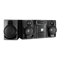
Overall specifications including power, dimensions, and weight.

Amplifier Section

Details on output power and impedance for amplifier stages.

Tuner Section

Frequency ranges for FM and AM tuning.

Cassette Deck Section

Specifications for cassette tape frequency response and S/N ratio.

Compact Disc Player Section

Details on CD player type, D/A converter, and frequency response.

Speaker Specifications

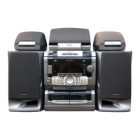
Specifications for front, center, rear, and subwoofer speaker units.

NAMES OF PARTS

Front Panel Components

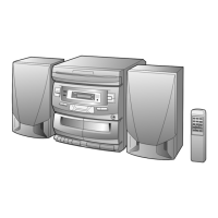
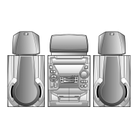
Identification of controls and indicators on the front panel.

Rear Panel Connectors

Identification of input/output jacks and terminals on the rear panel.

Speaker Component Identification

Front Speaker Details

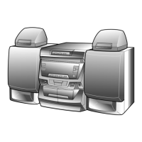
Identification of components for front speakers (CP-C472, CP-C3400/C3800).

Other Speaker Types

Identification of center, subwoofer, and rear speaker components.

Remote Control Functions

Remote Control Overview

Identification of primary remote control buttons and indicators.

Tuner, CD, and Tape Controls

Grouped controls for tuner, CD, and tape operations on the remote.

General Remote Functions

Identification of other remote functions like equalizer, power, and volume.

OPERATION MANUAL

Setting the Clock

Step-by-step instructions for setting the unit's clock.

Resetting the Microcomputer

Procedure to reset the microcomputer and clear memory contents.

MINI COMPONENT SYSTEM Quick-Guide

Preparation for Use and Basic Operations

Initial setup, CD, tape, radio playback, and sound control guidance.

Safety Precautions

Important warnings regarding volume levels and disc compatibility.

DISASSEMBLY

Disassembly Precautions

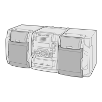
Important safety and handling notes before disassembling the unit.

Component Disassembly Steps

Step-by-step procedures for disassembling major unit components.

REMOVING AND REINSTALLING MAIN PARTS

CD Mechanism Section

Procedures for removing and reinstalling CD mechanism parts like motors and pickups.

ADJUSTMENT PROCEDURES

Mechanism Section Adjustments

Adjustments for tape mechanism driving force, torque, and speed.

Tuner Section Adjustments

Adjustments for AM IF/RF, FM RF, and VCO frequency.

TEST MODES AND CD SECTION

Setting and Using Test Modes

Procedures for setting and operating various test modes for the unit.

CD Section Automatic Adjustments

Information on automatic adjustment items for the CD pickup system.

DOLBY SURROUND PRO LOGIC EXPLANATION

Pro Logic Modes and Evaluation

Explanation of Dolby Pro Logic modes and evaluation methods.

Test Tone and InputOutput Relations

Procedures for test tone output and signal relations in Pro Logic modes.

NOTES ON SCHEMATIC DIAGRAM

Component Notation and Safety Notes

Explanations of resistor/capacitor notation and safety part markings.

WAVEFORMS OF CD CIRCUIT

BLOCK DIAGRAM (CD SECTION)

BLOCK DIAGRAM (TUNERTAPE SECTION)

BLOCK DIAGRAM (AUDIOCONTROL SECTION)

TROUBLESHOOTING (CD SECTION)

CD Functionality Issues

Troubleshooting for CD not functioning, turntable stop/move problems.

CD Tray and Operation Issues

Troubleshooting for CD tray open/close and general CD function problems.

CD SECTION TROUBLESHOOTING FLOWS

Playback and Key Operation Problems

Troubleshooting when playback is disc-dependent or keys are unresponsive.

CD PLAYBACK TROUBLESHOOTING

Disc Loading and Tracking Issues

Troubleshooting when playback requires a disc or tracking is unstable.

CD SYSTEM PERFORMANCE CHECKS

Spin System and VCO-PLL Troubleshooting

Steps to check spin system and VCO-PLL for disc rotation and signal issues.

No Sound Output Troubleshooting

Troubleshooting steps when no sound is emitted despite normal waveforms.

FUNCTION TABLE OF IC2

IC2 ServoSignal Control Details

Pinout and function details for IC2 (LC78623D) Servo/Signal Control.

IC2 FUNCTION TABLE (CONTINUED)

IC2 Block Diagram and Pin Functions

Block diagram and pin functions for IC2 (LC78623D).

FUNCTION TABLE OF IC1

IC1 Servo Amplifier Details

Pinout and function details for IC1 (LA9241M) Servo Amplifier.

IC1 FUNCTION TABLE (CONTINUED)

IC1 Block Diagram and Pin Functions

Block diagram and pin functions for IC1 (LA9241M).

FUNCTION TABLE OF IC701

IC701 System Microcomputer Details

Pinout and function details for IC701 (IX0192AW) System Microcomputer.

IC701 FUNCTION TABLE (CONTINUED)

IC701 Block Diagram and Pin Functions

Block diagram and pin functions for IC701 (IX0192AW).

FUNCTION TABLE OF IC501

IC501 Dolby Pro Logic Decoder Details

Pinout and function details for IC501 (LV1035M) Dolby Pro Logic Decoder.

FL Display Information

Information regarding the FL display unit (LCD701).

SHARP PARTS GUIDE

Component Parts Code Explanation

Guide explaining the coding system for capacitors and resistors.

PARTS LIST - INTEGRATED CIRCUITS & DISCRETE COMPONENTS

Integrated Circuits

List of integrated circuits with part codes and descriptions.

Transistors and Diodes

List of transistors and diodes with part codes and descriptions.

Filters, Transformers, Coils, Resistors, Vibrators, Capacitors

Lists of various electronic components with part codes and descriptions.

PACKING INSTRUCTIONS (For U.S.A. Only)

Setting Switches and Knobs for Packing

Instructions on setting switches and knobs before packing the unit.

Packing Components by Unit Type

Guidance on packing various unit types and accessories.

Accessories and PWB Assembly Details

Listing of accessories and Printed Wiring Board assemblies for packing.

Related product manuals