– 9 –
CD-C421H / C411H
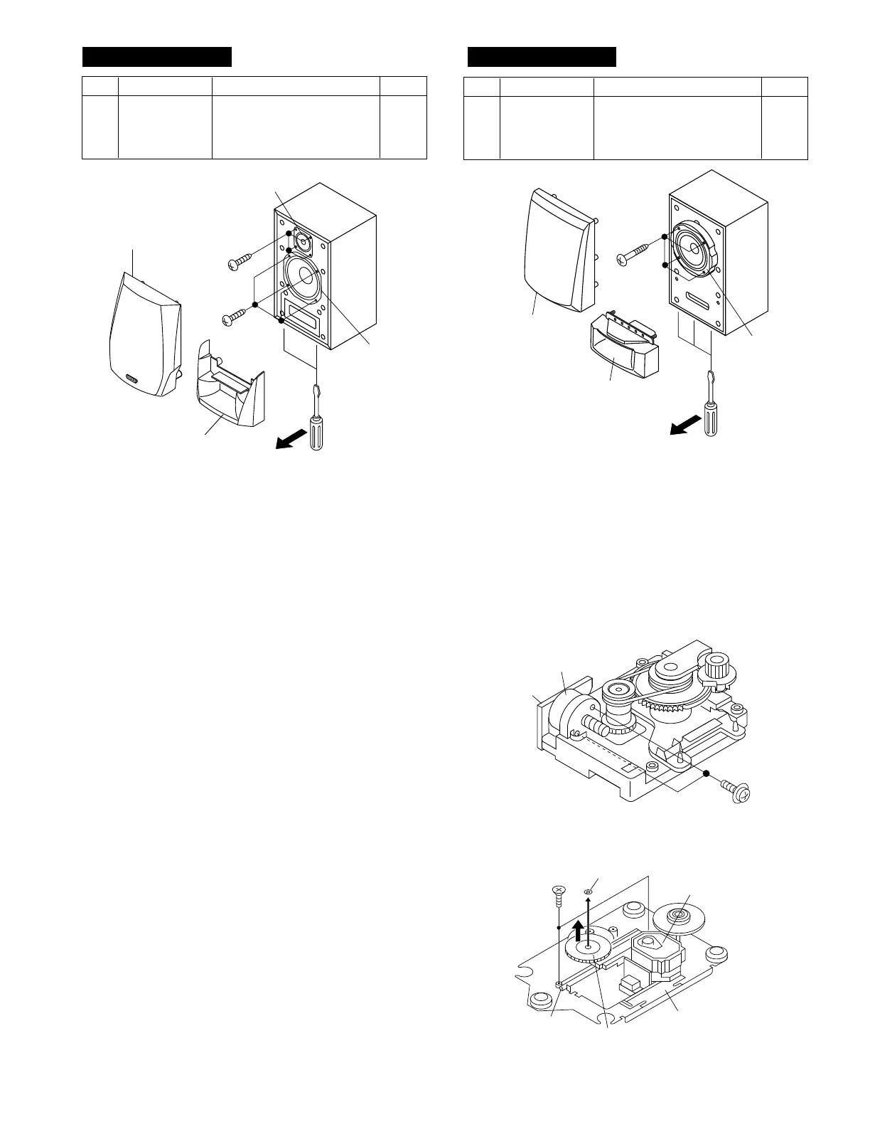
1 Front Speaker 1. Net Frame .............. (A1) x1 9-1
3. Duct Panel ............. (A2) x1
3. Screw ..................... (A3) x4
4. Screw ..................... (A4) x4
Figure 9-1
CP-C411HCP-C421H
STEP
REMOVAL PROCEDURE FIGURE
Screwdriver
Woofer
Tweeter
Net Frame
( A1 ) x1
( A3 ) x4
ø4x14mm
( A4 ) x4
ø4x14mm
Duct Panel
( A2 ) x1
Notes:
The Surround speakers (CD-C421H only) can be easily
disassembled.Therefore the disassembling method is not
discribed.For details refer to the disassembling drawing in the
Parts Guide.
Figure 9-4
Figure 9-3
How to remove the pickup (See Fig. 9-4)
1. Remove the screws (B1) x 2 pcs., to remove the shaft (B2)
x 1 pcs.
2. Remove the stop washer (B3) x 1 pc., to remove the gear
(B4) x 1 pc.
3. Remove the pickup.
REMOVING AND REINSTALLING THE MAIN PARTS
CD MECHANISM SECTION
Perform steps 1, 2, 3, 13 and 14 of the disassembly method
to remove the CD mechanism.
How to remove the loading motor
(See Fig. 9-3)
1. Remove the screws (A1) x 2 pcs., to remove the loading
motor.
( A1 ) x2
ø2.6 x5mm
Loading / Up
/ Down Motor
Motor
PWB
( B1 ) x2
ø2.6 x6mm
Shaft
( B2 ) x1
Stop Washer
( B3 ) x1
Gear
( B4 ) x1
CD Mechanism
Pickup
Figure 9-2
1 Front Speaker 1. Net Frame .............. (A1) x1 9-2
3. Duct Panel ............. (A2) x1
3. Screw ..................... (A3) x4
STEP REMOVAL
PROCEDURE
FIGURE
( A3 ) x4
ø3 x34mm
Screwdriver
Woofer
Net Frame
( A1 ) x1
Duct Panel
( A2 ) x1