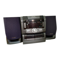
This document describes the SHARP CD-C421H and CD-C411H, which are compact disc digital audio systems. The CD-C421H model includes CP-C421H speakers and a surround sound system (GBOXS00018AWZZ), while the CD-C411H includes CP-C411H speakers.
Function Description:
The device is a multi-component audio system featuring a CD changer, an amplifier, a tuner, and a cassette deck. It supports various audio sources and playback modes.
CD Section:
The CD section features a 3-disc multi-play compact disc changer with a 3-beam semiconductor laser pickup. It supports CD play, repeat, and random/demo playback. The system includes indicators for disc number, play, pause, and repeat. Troubleshooting guides are provided for common CD issues, such as the turntable failing to stop or move, and the CD function not working. It also covers scenarios where playback is only possible when a disc is loaded, and issues with the VCO-PLL system or HF waveform.
Amplifier Section:
The amplifier section provides stereo output for both models, with the CD-C421H also supporting surround sound.
- CD-C421H:
- Output power (total): 120 W (MPO), 60 W (RMS 10% T.H.D.), 40 W (RMS 0.9% T.H.D.).
- Output power (front speakers): 30 W + 30 W (MPO), 20 W + 20 W (RMS 10% T.H.D.), 14 W + 14 W (RMS 0.9% T.H.D.).
- Output power (surround speakers): 10 W (MPO), 6 W (RMS 10% T.H.D.), 4 W (RMS 0.9% T.H.D.).
- Speakers: Front speakers (2-way, 10 cm woofer, 5 cm tweeter), Surround speakers (10 cm full-range).
- Impedance: Front speakers 6 ohms, Surround speakers 16 ohms.
- CD-C411H:
- Output power (total): 66 W (MPO), 33 W (RMS 10% T.H.D.), 20 W (RMS 0.9% T.H.D.).
- Output power (front speakers): 30 W + 30 W (MPO), 20 W + 20 W (RMS 10% T.H.D.), 14 W + 14 W (RMS 0.9% T.H.D.).
- Speakers: Front speakers (10 cm full-range).
- Impedance: Front speakers 6 ohms.
Tuner Section:
The tuner supports FM and AM bands.
- Frequency range: FM: 87.5-108 MHz, AM: 522-1,620 kHz.
- FM sensitivity: 14.2 dBf (mono), 40 dBf (stereo).
- FM signal-to-noise ratio: 50 dB (mono), 45 dB (stereo).
- AM sensitivity: 50 dB/m.
- RDS (Radio Data System) Operation: The system can display various RDS information such as Programme Service (PS), Programme Type (PTY), Traffic Programme (TP), and Traffic Announcement (TA). It also supports EON (Enhanced Other Networks) for enhanced traffic information. The ASPM (Automatic Station Program Memory) function allows for automatic memorization of stations.
Cassette Deck Section:
The cassette deck features a twin cassette compartment (TAPE1 and TAPE2) and supports normal and CrO2 tape types.
- Frequency response: 50-14,000 Hz (Normal tape), 50-15,000 Hz (CrO2 tape).
- Wow and flutter: 0.2% (WRMS).
Usage Features:
Front Panel Controls:
- Disc Tray, Disc Skip, Open/Close buttons.
- RDS, EON, TA, TP, TI, PTY indicators.
- Function/CD Track/CD Counter/Frequency/Preset Channel/Volume/Timer/Sleep Time Indicator.
- Sleep, FM Stereo Mode, FM Stereo, Extra Bass, Memory, Tape Play, Record, Timer Record, Timer Play indicators.
- On/Stand-by, Programme Type/Traffic Information Search, EON, Memory/Set, Record Pause, Extra Bass/Equalizer Mode, Function Selector, ASPM, Display Mode Selector, Clock, Timer/Sleep buttons.
- (CD) Track Down/Review, (TUNER) Preset Down buttons.
- Stop, Play/Repeat, (CD) Track Up/Cue, (TUNER) Preset Up buttons.
- Random/Demo, Volume Up/Down, Tuning and Time Up/Down buttons.
- Headphone Socket.
Rear Panel Connections:
- Speaker Terminals.
- AC Power Input Socket.
- Video/Auxiliary (Audio Signal) Input Sockets.
- FM 75 Ohms Aerial Socket.
- AM Loop Aerial Socket.
Remote Control:
The remote control provides comprehensive control over CD, tuner, and tape sections, including track selection, play/pause, stop, repeat, random, memory functions, and volume adjustment.
Setting the Clock:
The clock can be set in either 24-hour or 12-hour format. Instructions are provided for adjusting the hour and minutes, and for changing the time display mode. The clock display will flash after a power failure or disconnection of the AC power lead, indicating the need for time adjustment.
Resetting the Microcomputer:
The microcomputer can be reset to erase all stored memory contents, including clock and timer settings, and tuner and CD presets. This is also recommended if the display or operation is incorrect.
Maintenance Features:
Safety Precautions for Service:
- Laser Pickup: Special precautions are required when servicing the laser pickup due to invisible laser radiation. Do not stare into the beam or view directly with optical instruments. Laser output is max 0.6 mW (GaAIAs, 780 nm continuous).
- Withstanding Voltage Test (U.K. Only): After repair, a withstand voltage test must be performed to ensure user safety. The test involves applying 4,240 VPEAK (3,000 VRMS) for 6 seconds with a cutoff current of 4 mA.
Disassembly:
Detailed instructions are provided for disassembling the unit, including removing the top cabinet, side panels, CD player unit, disc tray, and various PWBs (Printed Wiring Boards). Specific steps are outlined for removing the turntable, CD mechanism, loading motor, and pickup.
Removing and Reinstalling Main Parts:
- CD Mechanism Section: Steps are provided for removing the CD mechanism, loading motor, and pickup. Care must be taken when installing the CD changer mechanism, ensuring the shift lever is in the highest position.
- Speakers: Instructions are given for disassembling the front speakers (CD-C421H and CD-C411H models). For the CD-C421H, the surround speakers are easily disassembled, with details available in the Parts Guide.
Adjustment:
- Mechanism Section: Includes procedures for checking driving force and torque for the cassette deck, and adjusting tape speed.
- Tuner Section: Provides adjustment points for AM IF/RF (T351, T306, T302) and FM Mute Level (VR351). Notes indicate that FM IF adjustment is not required in the field, as it is factory-adjusted.
- CD Section: Automatic adjustment items include focus error, tracking error, E/F balance, RF level, and RF level automatic follow-up of the tracking gain. Waveforms of the CD circuit are provided for reference during troubleshooting and adjustment.
Schematic Diagrams and Wiring:
The manual includes comprehensive schematic diagrams and wiring layouts for various PWBs, including the Display PWB, Main PWB, Headphone PWB, Power PWB, Tape Mechanism PWB, CD Motor PWB, Sensor PWB, and Tuner PWB. These diagrams are essential for troubleshooting and repair.
Troubleshooting:
Detailed troubleshooting flowcharts are provided for the CD section, covering issues such as the CD not functioning, the turntable failing to stop or move, and playback problems. These charts guide technicians through checks of voltage inputs, switch operations, IC outputs, and waveform analysis.
Function Table of ICs:
Detailed function tables are provided for key ICs, including IC2 (Servo/Signal Control), IC1 (Servo Amp), IC601 (Main System Microcomputer), and IC701 (Display System Microcomputer). These tables list pin numbers, terminal names, input/output types, and function descriptions, aiding in circuit analysis and fault diagnosis.
FL Display:
A diagram of the FL display (VVKBJ549GK-/1) is included, showing the various indicators for RDS, EON, PTY, TA, TP, PRO LOGIC, ST, 4-SP SLEEP, SRS, X-BASS, kHz, MHz, MEMORY, and REC.
Replacement Parts List/Exploded View:
The manual includes a replacement parts list and exploded views to assist with identifying and ordering replacement components.
Packing of the Set (U.K. Only):
Specific instructions for packing the set are provided for the U.K. market.