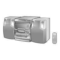
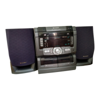
CD-C440W/CP-C440W
– 10 –
MECHANISM SECTION
• Driving Force Check
Torque Meter
Specified Value
Play: TW-2412 Tape 1: Over 80 g
Tape 2: Over 80 g
• Torque Check
Torque Meter
Tape 2
Play: TW-2111 30 to 60 g. cm 30 to 100 g.cm
Fast forward: TW-2231 — 50 to 100 g.cm
Rewind: TW-2231 — 50 to 100 g.cm
Specified
Value
Adjusting
Point
Instrument
Connection
Test Tape
Normal MTT-111 VRM1 3,000 ± Speaker
speed 30 Hz terminal
ADJUSTMENT
Specified Value
Tape 1
• Tape Speed
fL: Low-range frequency
fH: High-renge frequency
• AM IF/RF
Signal generator: 400 Hz, 30%, AM modulated
IF 450 kHz 1,602 kHz T351 *1
AM Band — 531 kHz (fL): T306 *2
Coverage 1.1 ± 0.1 V
AM 990 kHz 990 kHz (fL): T302 *1
Tracking
Test Stage Frequency
Frequency
Display
Setting/
Adjusting
Parts
Instrument
Connection
• FM
Notes:
1: Description of the "FM IF Adjustment" is not carried on this
Manual. It is because the IF coil in the FM front end section
has been best adjusted in the factory so that its further
adjustment is not needed at the field. When replacing the
FM front end assembly, no adjustment is needed either.
2: The parts in the FM front end section are prepared in a
complete unit, so you can't obtain each part individually
Adjusting
Parts
Instrument
Connection
Frequency
Display
Frequency
• FM Mute Level
Signal generator: 1 kHz, 40 kHz dev., FM modulated
98.00 MHz 98.00 MHz VR351* Input: Antenna
(25 dBµV) Output: Speaker
Terminal
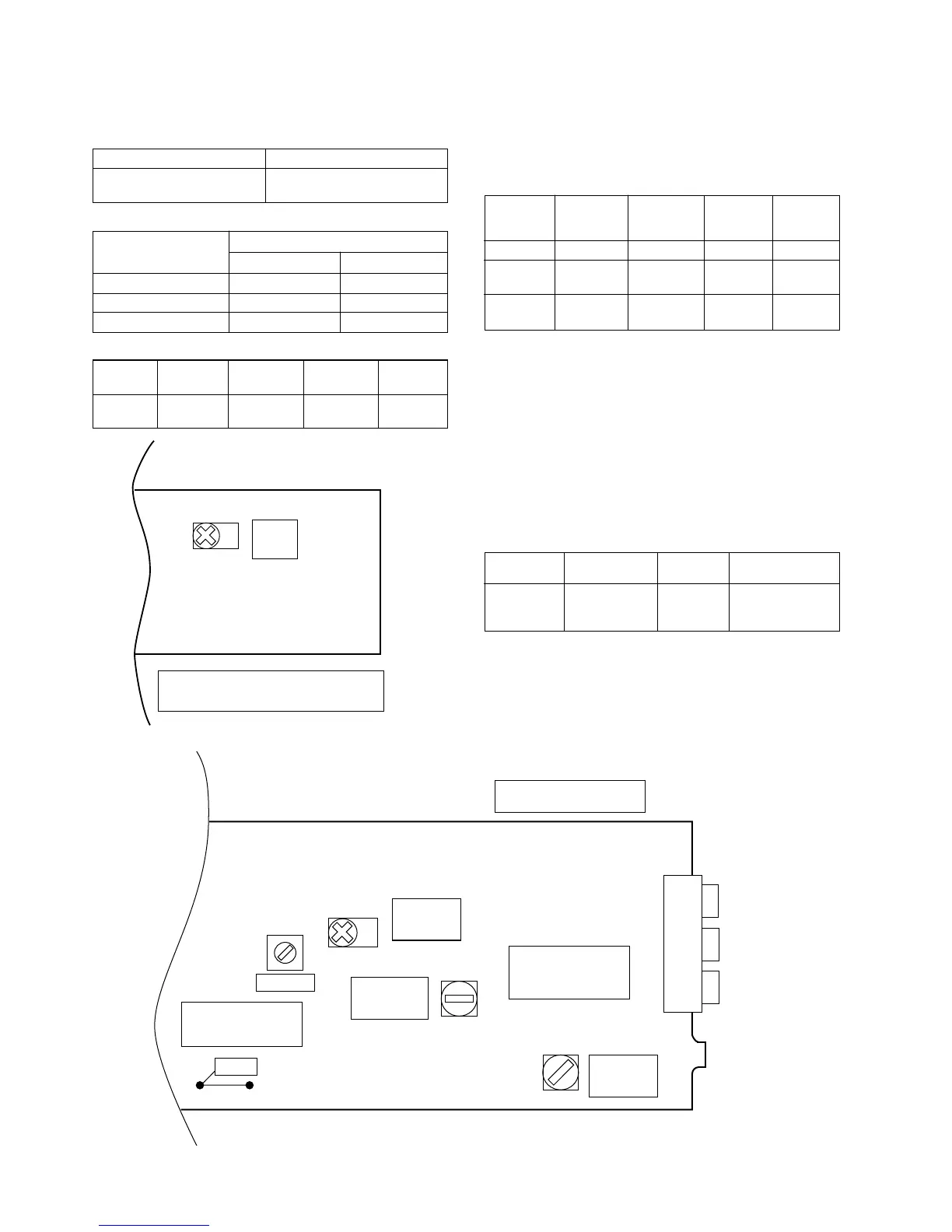
Figure 10 ADJUSTMENT POINTS
TUNER SECTION
*1. Input: Antenna, Output: TP302
*2. Input: Antenna, Output: TP301
TUNER PWB
SO301
ANTENNA
TERMINAL
FE301
TP302
T351
IC303
T306
T302
VR351
AM IF
FM MUTE
LEVEL
AM BAND
COVERAGE
AM
TRACKING
VRM1
TAPE
SPEED
TAPE MECHANISM PWB