CD-C811W/821W
– 1 –
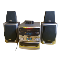
CD-C811W
CD-C821W
• In the interests of user-safety the set should be restored to its
original condition and only parts identical to those specified be
used.
SERVICE MANUAL
SHARP CORPORATION
No. S6938CDC811W/
This document has been published to be used
for after sales service only.
The contents are subject to change without notice.
CONTENTS
Page
SAFETY PRECAUTION FOR SERVICE MANUAL ............................................................................................................2
VOLTAGE SELECTION ..................................................................................................................................................... 2
SPECIFICATIONS ............................................................................................................................................................. 3
NAMES OF PARTS ........................................................................................................................................................... 4
OPERATION MANUAL ...................................................................................................................................................... 6
DISASSEMBLY.................................................................................................................................................................. 7
REMOVING AND REINSTALLING THE MAIN PARTS ..................................................................................................... 9
ADJUSTMENT ................................................................................................................................................................. 10
NOTES ON SCHEMATIC DIAGRAM .............................................................................................................................. 12
TYPE OF TRANSISTOR AND LED ................................................................................................................................. 12
BLOCK DIAGRAM ........................................................................................................................................................... 13
SCHEMATIC DIAGRAM / WIRING SIDE OF P.W.BOARD..............................................................................................18
WAVEFORMS OF CD CIRCUIT ...................................................................................................................................... 40
TROUBLESHOOTING ..................................................................................................................................................... 41
FUNCTION TABLE OF IC................................................................................................................................................ 45
FL SEGMENT ...................................................................................................................................................................52
PARTS GUIDE/EXPLODED VIEW
Illustration: CD-C811W
Illustration: CD-C821W
1
SECTION
CD-C811W
CD-C821W
Surround Speaker None Used
DIFFERENCE BETWEEN
CD-C811W AND CD-C821W
0.8
CD-C811W mini component system consisting of
CD-C811W (Main unit), CP-C811W (Front speaker).
CD-C821W mini component system consisting of
CD-C821W (Main unit), CP-C821W (Front speaker)
and GBOXS0028AWM1 (Surround speaker).