EasyManua.ls Logo

Sharp CD-C811W User Manual

Sharp CD-C811W
68 pages
To Next Page IconTo Next Page
Page #1 background imageLoading...
Page #1 background image
CD-C811W/821W
– 1 –
CD-C811W
CD-C821W
In the interests of user-safety the set should be restored to its
original condition and only parts identical to those specified be
used.
SERVICE MANUAL
SHARP CORPORATION
No. S6938CDC811W/
This document has been published to be used
for after sales service only.
The contents are subject to change without notice.
CONTENTS
Page
SAFETY PRECAUTION FOR SERVICE MANUAL ............................................................................................................2
VOLTAGE SELECTION ..................................................................................................................................................... 2
SPECIFICATIONS ............................................................................................................................................................. 3
NAMES OF PARTS ........................................................................................................................................................... 4
OPERATION MANUAL ...................................................................................................................................................... 6
DISASSEMBLY.................................................................................................................................................................. 7
REMOVING AND REINSTALLING THE MAIN PARTS ..................................................................................................... 9
ADJUSTMENT ................................................................................................................................................................. 10
NOTES ON SCHEMATIC DIAGRAM .............................................................................................................................. 12
TYPE OF TRANSISTOR AND LED ................................................................................................................................. 12
BLOCK DIAGRAM ........................................................................................................................................................... 13
SCHEMATIC DIAGRAM / WIRING SIDE OF P.W.BOARD..............................................................................................18
WAVEFORMS OF CD CIRCUIT ...................................................................................................................................... 40
TROUBLESHOOTING ..................................................................................................................................................... 41
FUNCTION TABLE OF IC................................................................................................................................................ 45
FL SEGMENT ...................................................................................................................................................................52
PARTS GUIDE/EXPLODED VIEW
Illustration: CD-C811W
Illustration: CD-C821W
1
SECTION
CD-C811W
CD-C821W
Surround Speaker None Used
DIFFERENCE BETWEEN
CD-C811W AND CD-C821W
0.8
CD-C811W mini component system consisting of
CD-C811W (Main unit), CP-C811W (Front speaker).
CD-C821W mini component system consisting of
CD-C821W (Main unit), CP-C821W (Front speaker)
and GBOXS0028AWM1 (Surround speaker).
Question and Answer IconNeed help?

Do you have a question about the Sharp CD-C811W and is the answer not in the manual?

Sharp CD-C811W Specifications

General IconGeneral
BrandSharp
ModelCD-C811W
CategoryStereo System
LanguageEnglish

Summary

Model Differences Between CD-C811W and CD-C821W

Safety Precautions for Service Manual

Voltage Selection

Procedure for selecting the correct AC voltage for the unit.

System Specifications

Component Identification Overview

Front Panel Parts Identification

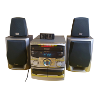
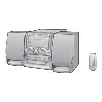
Identification of front panel controls and indicators.

Rear Panel Parts Identification

Identification of rear panel connectors and terminals.

Speaker System Parts Identification

Identification of front and surround speaker components.

Remote Control Parts Identification

Identification of remote control buttons and functions.

Operation Manual Procedures

Setting the Clock

Procedure for setting the unit's clock.

Remote Control and System Settings

Notes for remote control use and AM/FM interval, microcomputer reset.

Disassembly and Reassembly Procedures

Disassembly Cautions

Important safety and handling notes before disassembling the unit.

Main Part Removal Procedures

CD Mechanism Removal Steps

Steps for removing the CD mechanism and related parts.

Adjustment Procedures

Mechanism and Tuner Adjustments

Details on mechanism section and tuner section adjustments.

Test Mode and CD Troubleshooting

Test Mode Setup and CD Error Codes

Test mode setup, CD automatic adjustments, and error codes.

Block Diagrams

Schematic Diagrams

Wiring Side of P.W.Board

Waveforms of CD Circuit

Troubleshooting Guide

CD Section and Turntable Malfunctions

Diagnosing CD section failures and turntable stop issues.

Troubleshooting Guide (Cont.)

CD Tray and Control Malfunctions

Diagnosing CD tray and control failures.

Troubleshooting Guide (Cont.)

CD Operating Keys and Playback Issues

Diagnosing issues when CD controls work but playback fails.

Troubleshooting Guide (Cont.)

CD System Checks and Sound Output

Checking CD systems and diagnosing no sound output issues.

IC Function Tables

IC1 Servo Amp. Function Table

Pin functions for the IC1 servo amplifier.

IC Function Tables (Cont.)

IC3 Driver and IC401 Audio Processor Function Tables

Pin functions for IC3 driver and IC401 audio processor.

IC Function Tables (Cont.)

IC2 Servo/Signal Control Details (1/2)

Pin functions for the IC2 servo/signal control IC.

IC Function Tables (Cont.)

IC2 Servo/Signal Control Details (2/2) & IC701 Microcomputer Details (1/2)

Pin functions for IC2 servo/signal control and IC701 microcomputer.

IC Function Tables (Cont.)

IC701 Microcomputer Details (2/2)

Pin functions for the IC701 microcomputer.

IC Function Tables (Cont.)

IC701 Microcomputer Details (1/2) (CD-C821W)

Pin functions for IC701 microcomputer on CD-C821W.

IC Function Tables (Cont.)

IC701 Microcomputer Details (2/2) (CD-C821W)

Pin functions for IC701 microcomputer on CD-C821W.

FL Display Pinout Information

Parts Guide

How to Order Replacement Parts

Instructions on how to order replacement parts.

Component Identification Codes

Explanation of codes used for capacitor and resistor part numbers.

Component Parts Lists

ICs, Transistors, Diodes, Coils, Resistors

Parts list for ICs, transistors, diodes, coils, and resistors.

Capacitors, Variable Resistors, and Other Components

Parts list for capacitors, variable resistors, vibrators, and other components.

Resistors Parts List

Other Circuitry Parts List

Speaker System Parts List

Front and Surround Speaker Box Parts

Parts list for front and surround speaker boxes.

CD Mechanism and Cabinet Parts

CD Mechanism Components

List of parts for the CD mechanism assembly.

Main Unit Cabinet Parts

List of parts for the main unit's cabinet assembly.

Related product manuals