CD-PC671H/PC651H
– 12 –
• AM IF/RF
Signal generator: 400 Hz, 30%, AM modulated
*1. Input: Antenna, Output: TP302
*2. Input: Antenna, Output: TP301
TUNER SECTION
fL: Low-range frequency
fH: High-renge frequency
IF 450 kHz 1,620 kHz T351 *1
Band — 522 kHz (fL): T306 *2
Coverage 1.1 ± 0.1 V
Tracking 990 kHz 990 kHz (fH): T302 *1
Test Stage Frequency
Frequency
Display
Setting/
Adjusting
Parts
Instrument
Connection
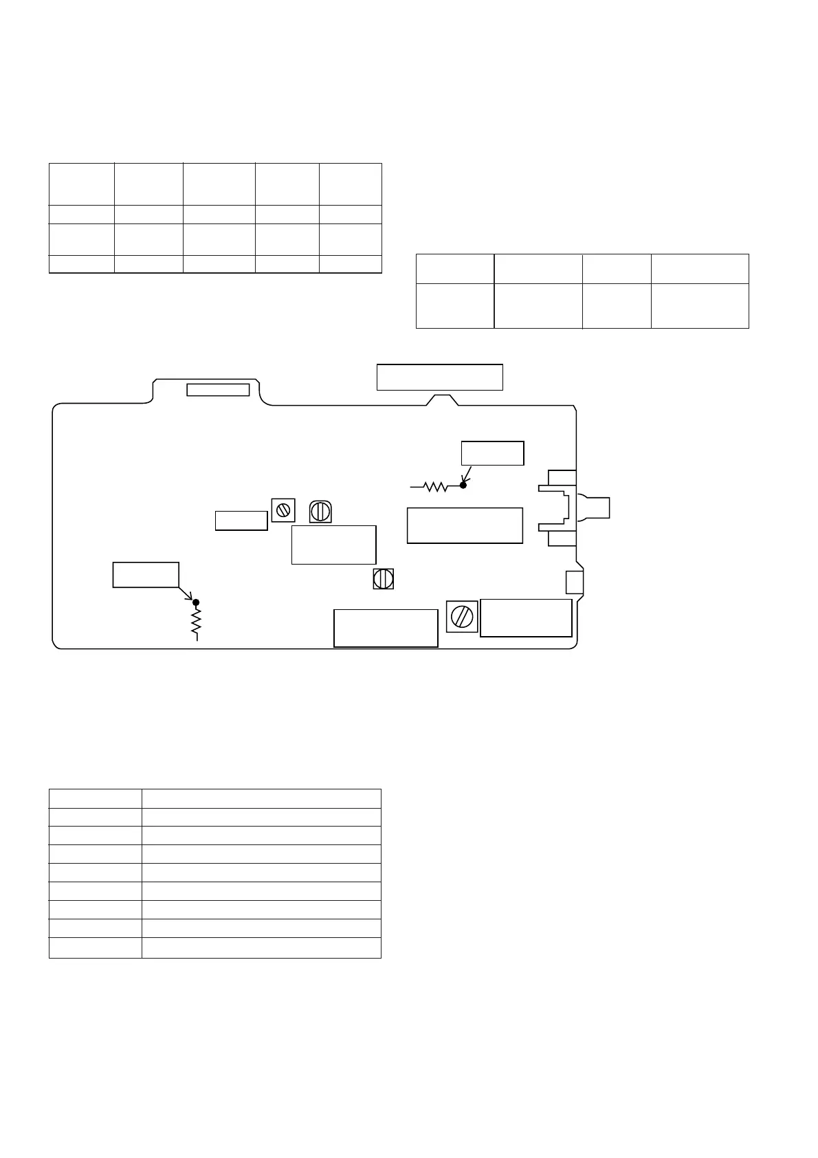
Figure 12 ADJUSTMENT POINTS
CD ERROR CODE DESCRIPTION
When a malfunction occurs during CD operation, an error
code will be displayed to identify the function in CD operation
which failed.
Error State Code
0001 Cannot detect pickup-in SW
0101 Tray close operation error
0105 Tray close operation error
0201 Tray open operation error
0203 Tray open operation error
0304 Disc skip operation error
0305 Disc skip operation error
0307 Disc skip operation error
• FM
Notes:
1: Description of the "FM IF Adjustment" is not carried on this
Manual. It is because the IF coil in the FM front end section
has been best adjusted in the factory so that its further
adjustment is not needed at the field. When replacing the
FM front end assembly, no adjustment is needed either.
2: The parts in the FM front end section are prepared in a
complete unit, so you can't obtain each part individually
Adjusting
Parts
Instrument
Connection
Frequency
Display
Frequency
• FM Mute Level
Signal generator: 1 kHz, 40 kHz dev., FM modulated
98.00 MHz 98.00 MHz VR351 Input: Antenna
(25 dBµV) Output: Speaker
Terminal
TP302
R357
T351
VR351
FM MUTE
LEVEL
R336
TP301
FE301
T306
T302
SO301
FM ANTENNA
TERMINAL
CNP301
AM LOOP
ANTENNA
TERMINAL
TUNER PWB
CNP303
AM IF
AM BAND
COVERAGE
AM
TRACKING