EasyManua.ls Logo

Sharp CD-E600 User Manual

Sharp CD-E600
44 pages
To Next Page IconTo Next Page
Page #1 background imageLoading...
Page #1 background image
CD-E600/CD-E66
No. S1306CDE600//
CONTENTS
Page
IMPORTANT SERVICE NOTES (FOR U.S.A. ONLY)....................................................................................................... 2
SPECIFICATIONS ............................................................................................................................................................. 3
NAMES OF PARTS ........................................................................................................................................................... 4
DISASSEMBLY.................................................................................................................................................................. 6
BLOCK DIAGRAM ............................................................................................................................................................. 9
SCHEMATIC DIAGRAM / WIRING SIDE OF P.W.BOARD............................................................................................. 12
NOTES ON SCHEMATIC DIAGRAM .............................................................................................................................. 29
TYPES OF TRANSISTOR AND LED............................................................................................................................... 29
VOLTAGE ........................................................................................................................................................................ 30
WAVEFORMS OF CD CIRCUIT...................................................................................................................................... 31
FL DISPLAY..................................................................................................................................................................... 32
REPLACEMENT PARTS LIST/EXPLODED VIEW
PACKING OF THE SET (FOR U.S.A. ONLY)
SERVICE MANUAL
This document has been published to be used
for after sales service only.
The contents are subject to change without notice.
SHARP CORPORATION
In the interests of user-safety the set should be restored to its
original condition and only parts identical to those specified be
used.
Illustration: CD-E600
MINI COMPONENT SYSTEM
MODEL CD-E600
CD-E600 Mini Component System consisting of CD-E600
(main unit) and CP-E600 (speaker system).
MINI COMPONENT SYSTEM
MODEL CD-E66
CD-E66 Mini Component System consisting of CD-E66 (main
unit) and CP-E66 (speaker system).
CD-E700/CD-E77
Page
REMOVING AND REINSTALLING THE MAIN PARTS.. 9
ADJUSTMENT .............................................................. 10
TROUBLESHOOTING .................................................. 37
FUNCTION TABLE OF IC............................................. 41
This Service Manual is for the CD-E600/CD-E66, which is a
minor-modification model of the CD-E700/CD-E77, This
manual, therefore, describes only the changed points from
the service manual. Please refer to the CD-E700/CD-E77,
service manual (No. S1301CDE700//) together with this
manual.
jomi
Question and Answer IconNeed help?

Do you have a question about the Sharp CD-E600 and is the answer not in the manual?

Sharp CD-E600 Specifications

General IconGeneral
TypeStereo System
BrandSharp
ModelCD-E600
CD PlayerYes
TunerFM/AM
Weight (main unit)3.5 kg
BluetoothNo
USB PortNo
Output Power2 x 20W
Playable MediaCD

Summary

Important Service Notes

Safety Checks Before Returning Product

Perform safety checks like lead dress, protective devices, and leakage current before returning the unit.

System Specifications

CD-E600/CD-E66 Specifications (USA & Canada)

Detailed technical specifications for the main unit in USA and Canada.

Speaker System Specifications (CP-E600/CP-E66)

Technical specifications for the speaker systems in USA and Canada.

Component Identification

Front Panel Controls and Indicators

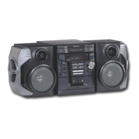
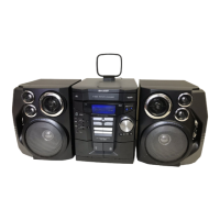
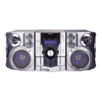
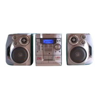
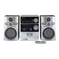
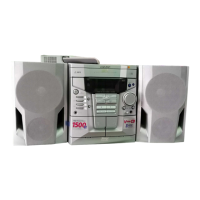
Identifies and lists components on the front panel and display indicators.

Rear Panel Connections

Identifies components located on the rear panel of the main unit.

Remote Control Operation

Remote Control Transmitter Functions

Lists and describes the functions of each button on the remote control transmitter.

Speaker System Components (CP-E600/CP-E66)

Identifies the components of the CP-E600/CP-E66 speaker systems.

Disassembly Procedures

Disassembly Safety and Handling Notes

Safety and performance precautions to follow during disassembly and reassembly.

Main Unit Disassembly Steps

Step-by-step guide for disassembling the main unit, referencing figures and parts.

CD Mechanism Disassembly Steps

Specific steps for disassembling the CD mechanism, including optical pickup handling.

Disassembly Procedures (cont.)

Speaker System Removal Steps

Step-by-step guide for removing components from the speaker systems.

Block Diagrams

Block Diagram (1/3) - CD Servo and Drivers

Overview of the CD servo system and associated driver ICs.

Block Diagram (2/3) - Tuner and Audio Processor

Overview of the tuner section and audio processor circuitry.

Block Diagram (3/3) - Microcomputer and Power Amp

Overview of the system microcomputer, power amplifier, and voltage regulators.

Schematic Diagrams

Schematic Diagram (1/10) - Audio Processor and Playback Amp

Detailed circuit diagram for the audio processor and playback amplifier section.

Schematic Diagram (2/10) - Main PWB and Tuner Section

Circuit diagram of the main PWB and the tuner circuitry.

Schematic Diagram (3/10) - FM Front End and Tuner IC

Circuit diagram for the FM front end and tuner integrated circuits.

Schematic Diagram (4/10) - Tuner IC and FM MPX/AM IF

Circuit diagram for the tuner IC and FM MPX/AM IF sections.

Schematic Diagrams (cont.)

Schematic Diagram (5/10) - Power Amplifier and Voltage Regulators

Circuit diagram for the power amplifier and voltage regulator circuits.

Schematic Diagram (6/10) - Power Supply and Transformer Circuits

Circuit diagram for the power supply and transformer sections.

Schematic Diagram (7/10) - LEDs and Tape Mechanism Control

Circuit diagram for LEDs and tape mechanism control signals.

Schematic Diagram (8/10) - Microcomputer and Key Inputs

Circuit diagram for the system microcomputer and key input interfaces.

Schematic Diagrams (cont.)

Schematic Diagram (9/10) - CD Servo PWB and Motor Drivers

Circuit diagram for the CD servo PWB and motor driver ICs.

Schematic Diagram (10/10) - CD Servo Block and Loading Motor

Circuit diagram detailing the CD servo block and loading motor connections.

PWB Wiring Diagrams

PWB Wiring Diagram (1/7) - Main PWB

Wiring layout for the main PWB, showing component placement.

PWB Wiring Diagram (2/7) - Main PWB and Tape Mechanism

Wiring layout for the main PWB and tape mechanism connections.

PWB Wiring Diagram (3/7) - Display PWB and Tape Mechanism

Wiring layout for the display PWB and tape mechanism interfaces.

PWB Wiring Diagram (4/7) - LED PWB and Control Switches

Wiring layout for the LED PWB and control switch connections.

PWB Wiring Diagrams (cont.)

PWB Wiring Diagram (5/7) - CD Servo PWB and CD Motor

Wiring layout for the CD servo PWB and CD motor connections.

PWB Wiring Diagram (6/7) - Tape Mechanism PWB and Connections

Wiring layout for the tape mechanism PWB and associated connections.

PWB Wiring Diagram (7/7) - Power PWB and Transformers

Wiring layout for the power PWB, transformers, and AC cord connection.

Schematic Diagram Notes

Resistor and Capacitor Notation Explanation

Explains notation used for resistors and capacitors in schematic diagrams.

Voltage Measurement Reference

Notes on how voltages are measured and indicated in the manual.

Safety Precautions for Parts Replacement

Importance of replacing parts marked with 'A' for safety and performance.

Transistor and LED Identification

Transistor Part Numbers and Types

Lists part numbers and types for various transistors with front view identification.

LED Part Numbers and Types

Lists part numbers and types for various LEDs with front view identification.

Voltage Specifications

IC Voltage Readings

Lists pin numbers and corresponding voltage readings for various ICs.

CD Circuit Waveform Analysis

Waveforms 1-4: IC1 FDO/TDO/DRF/TE Signals

Analyzes IC1 FDO, TDO, DRF, and TE signal waveforms during operation.

Waveforms 5-8: IC1 FDO/PD01 Signals

Analyzes IC1 FDO and PD01 signal waveforms under different conditions.

Waveforms 9-12: IC1 DOUT/DATA/DATACK Signals

Analyzes IC1 DOUT, DATA, and DATACK signal waveforms for CD circuit operation.

FL Display Information

FL Display Grid Assignment Details

Shows grid assignments for characters and symbols on the FL display.

FL Display Anode Connection Details

Details the anode connections for each segment of the FL display.

Parts Code Explanations

Capacitor Part Code Explanations

Explains codes used for capacitor types, capacitance, and tolerance.

Resistor Part Code Explanations

Explains codes used for resistor types, resistance, and tolerance.

Safety Notes for Fuses and Parts

Cautions regarding fire hazard protection and component replacement for safety.

Component Parts List - ICs, Transistors, Diodes, Filters/Transformers

Integrated Circuits List

Lists integrated circuit part numbers, descriptions, and associated codes.

Transistors List

Lists transistor part numbers, types, and silicon characteristics.

Diodes List

Lists diode part numbers, types, and silicon characteristics.

Filters and Transformers List

Lists part numbers for filters and transformers.

Component Parts List (cont.)

Capacitors List

Lists capacitor part numbers, types, capacitance, and tolerance.

Resistors List

Lists resistor part numbers, types, resistance, and tolerance.

Other Circuitry and Mechanism Parts

Other Circuitry Parts Identification

Lists various parts like connectors, wires, fuses, relays, and fans.

CD Mechanism Component Parts List

Lists parts specific to the CD mechanism, like gears and motors.

Cabinet Component Parts List

Lists parts for the main unit cabinets and panels.

Other Service and Speaker Parts

Other Service Parts List

Lists various service parts including screws, cushions, and covers.

Speaker Box Parts List

Lists parts for the speaker boxes, including drivers and cabinets.

Speaker, Packing, and Miscellaneous Parts

Speaker Box Parts List (cont.)

Lists parts for speaker boxes, including screws and radiators.

Packing Parts List

Lists packing materials for the set, excluding the USA.

CD Mechanism Exploded View

CD Mechanism Exploded View Diagram

Exploded view diagram of the CD mechanism, showing component layout.

Cabinet Exploded Views

Main Unit Cabinet Exploded View (Part 1)

Exploded view of the main unit cabinet, showing internal PWB and component layout.

Main Unit Cabinet Exploded View (Part 2)

Exploded view of the main unit cabinet, showing external panels and mechanism.

Speaker System Exploded View

Speaker System Exploded View Diagram

Exploded view diagram of the speaker system, showing drivers and cabinet parts.

Packing of the Set (USA)

USA Packing Procedure and Contents

Illustrates the packing process for the CD-E600/CD-E66 set in the USA.

Related product manuals