CHAPTER 3. SPECIFICATIONS OF
RS-232 INTERFACE
1. Online interface
a) Interface : RS-232
b) Duplex type : Half-duplex / Full-duplex
c) Line configuration : Direct connection/Modem connection
d) Data rate : 19200, 9600, 4800, 2400, 1200, 600 and
300 bps
(Programable)
e) Synchronizing mode : Asynchronous
f) Parity check : Vertical parity check (odd)
g) Code : ASCII
h) Bit sequence : LSB first
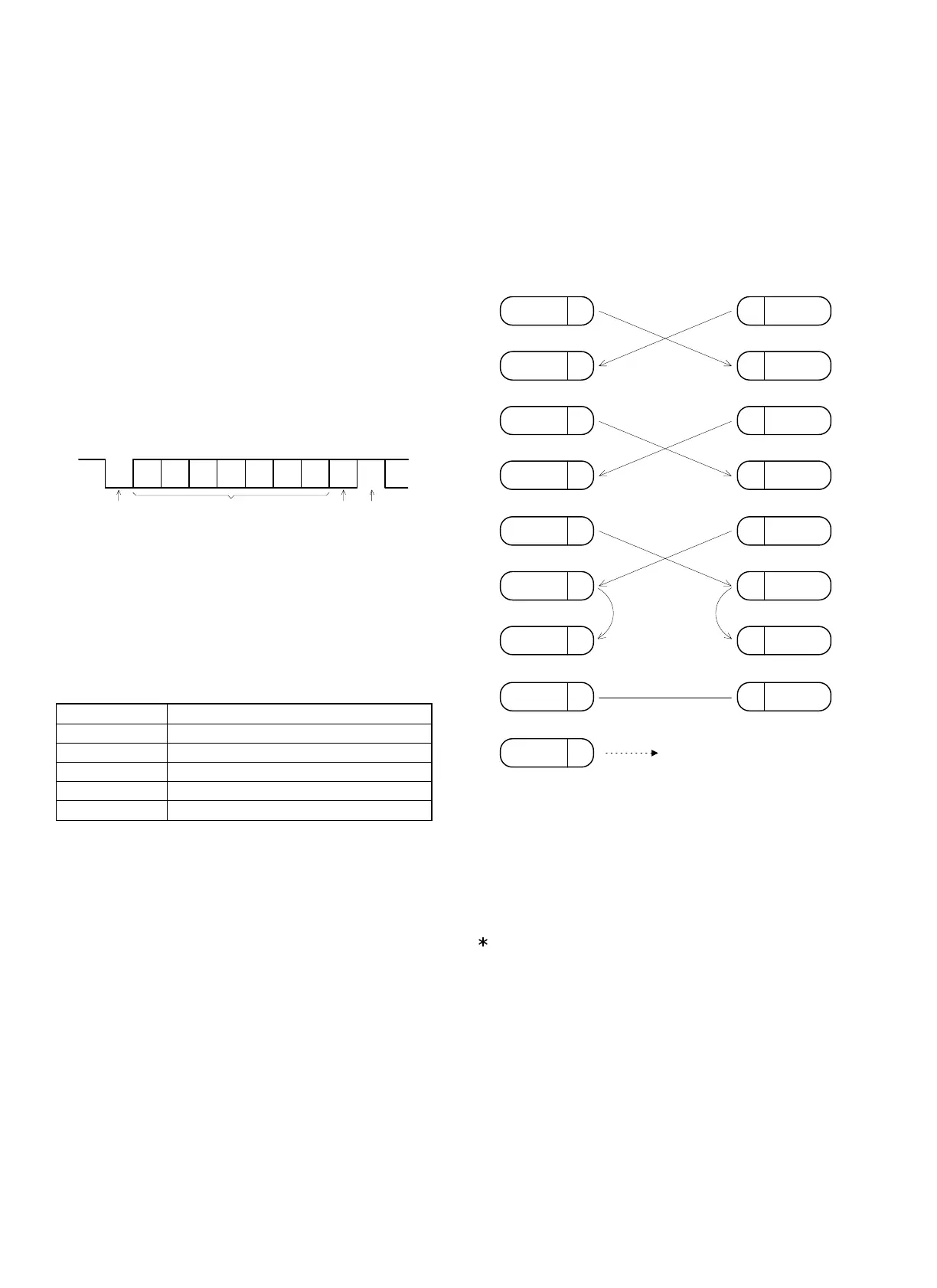
i) Data format : 1 start bit + 7 data bits + 1 parity +
1 stop bit
j) Protocol : Polling/selecting (Simple procedure)
k) Transmission line :
Cable : Shielded cable
Connector
(ECR side)
: D-sub 9 pin (female type) connector
Inch pitch (4-40 UNC) lock screw
Connector cover : Shielded cover
The table shows the relationship between the data rate and the rec-
ommended cable length.
Data rate Recommended cable length
19,200 bps 3.75 meters
9,600 bps 7.5 meters
4,800 bps 15 meters
2,400 bps 30 meters
1,200 bps 60 meters
CHAPTER 4. SIGNAL CONNECTION
DIAGRAM
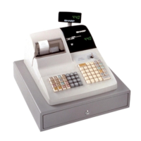
1. Connection between the master (Host)
and Satellite
SD : TRANSMITTED DATA
RD : RECEIVED DATA
DTR : DATA TERMINAL READY
DSR: DATA SET READY
RTS : REQUEST TO SEND
DCD: DATA CARRIER DETECTOR
CTS : CLEAR TO SEND
FG : FRAME GROUND
If the connector of Host side is "9 PIN D-SUB", the pin number is
same as Satellite side.
Data-bit
Parity-bit Stop-bit
b1 b2 b3 b4 b5 b6 b7
P
Start-bit
SD
2
SD
RD
CTS
RD
3
6
5
3
2
6
8
HOST
75
SG
RTS
4
DCD
8
DTR
20
DSR
7
1
4
SATELLITE
CTS
SG
RTS
DCD
DTR
DSR
1
FG
FRAME GROUND is connected
to the shield of the cable.
25PIN D-SUB 9PIN D-SUB
– 2 –