Do you have a question about the Sharp GF-575Z and is the answer not in the manual?
General specifications including power, speakers, output, semiconductors, dimensions, and weight.
Specifications for tape frequency response, S/N ratio, wow/flutter, input/output impedance.
Radio frequency ranges for AM, SW1, SW2, and FM bands.
Procedure for selecting the correct mains voltage for operation.
Instructions for removing the front, back, and main frame cabinets.
Steps for removing the tuner frame and record/playback P.W.B.
Circuitry for selecting tape playback and recording speeds.
Details on the Automatic Program Pause System functionality.
Steps for adjusting bias, erase current, and sensitivity for the record amplifier.
How to check and calibrate the unit's level meter sensitivity.
Adjustments for normal tape speed operations on both decks.
Adjustments for high tape speed operations, particularly dubbing.
How to identify and compare chip resistors, capacitors, and jumpers with standard types.
Procedures for removing, attaching, and handling leadless chip components.
| Country | Japan |
|---|---|
| Manufacturer | Sharp |
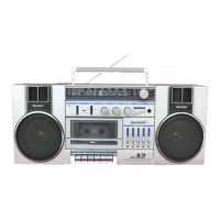
| Model | GF-575Z |
| Power Source | AC/DC |
| Cassette Deck | Double Cassette Deck |
| Weight | 7.5 kg |
| Tuner | FM/AM |
| Frequency Range | FM: 87.5-108 MHz, AM: 530-1605 kHz |