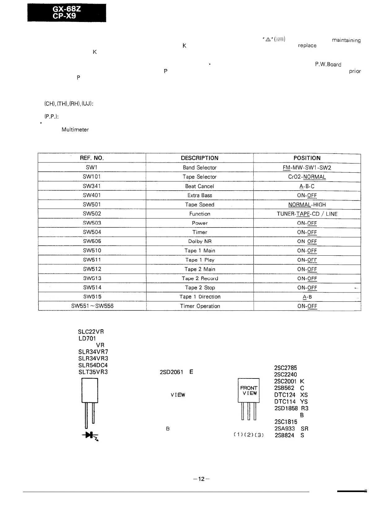
NOTES ON SCHEMATIC DIAGRAM
. Resistor:
. Parts marked with
“A”
(-243)
are important for
maintaining
To differentiate the units of resistors, such symbol as
K
is
the safety of the set. Be sure to
rePlaCe
these parts with
used: the symbol
K
means 1000 ohm and the resistor
specified ones for maintaining the safety and performance
without any symbol is ohm-type resistor.
of the set.
. Capacitor:
*
Schematic diagram and Wiring Side of
P.W.Board
for this
To indicate the unit of capacitor, a symbol
P
is used:
model are subject to change for improvement without
prior
this symbol
P
means micro-micro-farad and the unit of
notice.
the capacitor without such a symbol is microfarad. As to
electrolytic capacitor, the expression “capacitance/withstand
voltage” is used.
(CH),
(TH),
(RH),
(UJ):
Temperature compensation
(ML): Mylar type
(P.P.):
Polypropylene type
*
The indicated voltage in each section is the one measured by
Digital
Multimeter
between such a section and the chassis
with no signal given.
SLC22UR
LD701
DU
LD701
UR
SLR34UR7
SLR34UR3
SLR54DC4
SLT35UR3
2SD2061
E
FRON
VIEW
a
8
CE
2SC2785
EF
2SC2240
BL
rl
2SC2001
K
FRONT
2SB562
C
VIEW
DTC124
XS
II-n-f
ECB
DTC114
YS
2SD1858
R3
2562878
B
2SC.1815 GR
2SA933
SR
(l)(2)(3)
2S8824
S
Figure 12 TYPES OF TRANSISTOR AND LED
-12-
 Loading...