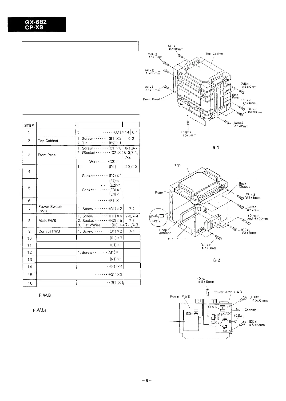
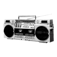
DISASSEMBLY
Caution on Disassembly
Follow the below-mentioned notes when disassembling the
unit and reassembling it, to keep its safety and excellent
performance:
1. Take cassette tape of the unit.
2. Be sure to remove the power supply plug from the
wall outlet before starting to disassemble the unit and
remove the batteries from the unit.
3. Take off nylon bands, wire holders or connectors where
they need be removed when disassembling the unit.
After servicing the unit, be sure to rearrange the leads
where they were before disassembling.
4. Take sufficient care on static electricity of integrated
circuits and other circuits when servicing.
1
15
t
16
-t
i
(Allxl
03xlOmm
REMOVAL
I
PROCEDURE
1
FIGURE
1
Side Panel
(7. Screw
..+Al)xl4(
6-l
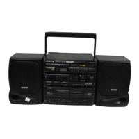
/
~‘““:::::::
2.
Socket........(C2)X4
6-3.7-1,
Power Amp. PWB
3. Flat Wire. . . . .
(C3)
X
3
6-3
1.
Screw . . . . . . .
.iDl)
X9
6-2.6-3,
7-l
Volume PWB
Timer PWB
2.
Socket........(D2)Xl
6-3
1. Knob
. . . . . . .
(El
)
x
,
7-2
2. Nut
. . . . .
*
.
*
. .
(E2)
x
1
3.
Socket*..-....(EB)Xl
/
4. Flat Wire
......
(E4)
X
2
/
1. Screw
........(F~)x
2
/
7-4
5_~
3. Flat
Wire......(HB)X4
7-1.7-3
Mechanism Block
I
1. Screw .
. . . . .
..(KliX71
7-4
j
Headphones PWB
Tape Switch PWB
Microphone PWB
1. Screw
. . . . . . . .
(Ll)X,
7-4
I.
Screw..
. .
*.
.
.(Ml
)
X
1
7-4
1. Screw
. . . . . . . .
(Nl)xl
7-4
Level Meter PWB
/
1. Hook
. . . . . .
..(Pl)X41
7-4
1
Remote Control
PWR
1. Hook
.......
.(0,)x2!
7-4
(
LED PWB
/
1.
Screw
. . . . .
..(Rl)xl
1
7-4
1
k(Al)x2
03xl2mm
I
(Cl1x3
63x8mm
Figure 6-1
hop
Cabinet
Front
Panel
Main Chassis
*Each P.W.B should be removed until the parts to be
exchanged can be removed when servicing. If the parts to
be exchanged are in the exchangeable condition, the rest
of P.W.Bs need not to be removed.
Power
Transformer
(Dl)xZ
03x8mm
Figure
6-2
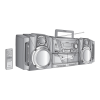
(Dl)x
I
03x6mm
.(Cl)X2
03x6mm
-6-