GX-CD30/30C/130/130C
MECHANISM SECTION
• Driving Force Check
PLAY: TW-2412 Tape 1: Over 50 g
Tape 2: Over 100 g
Torque Meter
Specified Value
• Torque Check
Torque Meter
Specified Value
Play: TW-2111 30 to 60 g.cm 30 to 60 g.cm
Fast Forward: TW-2231 80 to 135 g.cm
Rewind: TW-2231 80 to 135 g.cm
Tape 1 Tape 2
• Tape Speed
Nomal MTT-111 3,000 Speaker
speed ± 30 Hz terminal
(Load resistance:
6 ohms)
Instrument
Connection
Specified
Value
Test Tape
TAPE SECTION
Position of each switch or control
Volume control Max
Beat cancel A
Function/Power switch Tape/Off
• Bias Oscillation Check
Beat cancel A: 82 + 10 kHz / -6 kHz
B: -2 ± 2 kHz
C: +3 ± 2 kHz
Specified Value
• Erase Current Check
Specified Value
Resistor for measurement: 1 ohm 50 ± 25 mV
• Playback Amplifier Sensitivity Check
Instrument ConnectionTest Tape
MTT-118 1.8 V ± 3 dB Speaker Terminal
(Load resistance: 6 ohms)
Specified Value
ADJUSTMENT
TUNER SECTION
fL: Low-range frequency
fH: High-range frequency
• FM IF/RF
IF T1
Detection T2
Band Coverage fL: L2
fH: TC2
Tracking 88.0 MHz: L1
108.0 MHz: TC1
Test Stage
Specified
Value/Adjusting
Point
Instrument
Connection
Input: Pin 1 of IC1
Output: Pin 17 of IC2
Iuput: Antenna
Output: Headphones
Socket (Load
resistance: 32 ohms)
• AM IF/RF
IF T3 Input: Antenna
Output: Pin 19 of IC2
Band Coverage fL: L4 Input: Antenna
fH: TC4 Output: Headphones
Tracking 600 kHz: L3 Socket (Load
1,400 kHz: TC3 resistance: 32 ohms)
Test Stage
Specified
Value/Adjusting
Point
Instrument
Connection
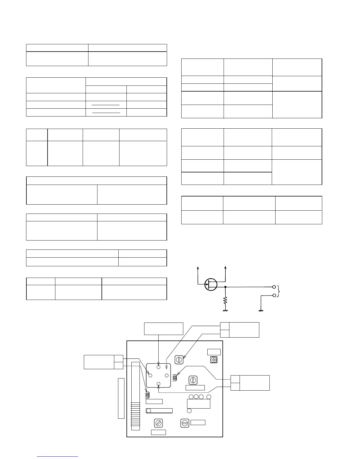
• VCO Frequency
Specified
Value
Instrument
Connection
VR1 76 kHz ± 200 Hz Pin 13, pin 21 and
ground of IC2
Adjusting Point
Note:
After preparing the test circuit shown in Fig. 8-1, connect the
Pin 13, Pin 21 and ground of the IC2 with the test circuit, and
measure the value. At this time, apply a standard unmodulated
signal input and adjust the VCO.
– 8 –
Pin 13 of IC2 Pin 21 of IC2
D
G
S
10 kohm
TO FREQUENCY
COUNTER
FET : 2SK19 or 2SK54
Figure 8-1 VCO FREQUENCY TEST CIRCUIT
AM TRACKING
fH
AM BANDfH
fL
COVERAGE
FM
AM TRACKING fL
AM BARANTENNA
fH
fL
TRACKING
FM BANDfL
fH
COVERAGE
VCO
L4
VR1
TC4
TC3
TC1
1
TC2
L2
L1
L3
T2
T1
T3
FM DET
AM IF
FM IF
FM RF
IC2
IC1
13
1
17
19
21
Figure 8-2 ADJUSTMENT POINTS