28
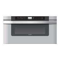
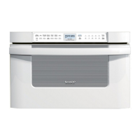
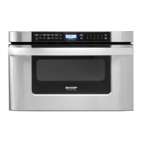
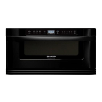
KB-6524PSY KB-6525PSY
DRAWER/SLIDE RAIL REMOVAL
DRAWER ASSEMBLY AND CHOKE REMOVAL
Fig. D-1
Fig. D-2
Fig. D-3
Fig. D-7
Door Support Angle A
Door
Support
Cover
Door
Support
Cover
Fig. D-4
Fig. D-6
Door Support Angle B
Rack Gear
1. Open the drawer, remove Oven Tray and keep it open.
2. Remove (2) Drawer Support Covers from Choke Cover as
shown in (Fig. D-1).
3.
Remo
ve (4) screws from both Door Support Angles A as
shown in (Fig. D-2).
4.
Unhook bottom Door Suppor
t Angle B from drawer by moving
black inside lever to the side to release the drawer from the
Slide rail by pulling it out (Fig. D-3).
5.
The Dr
awer assembly is free and the Choke Cover can now
be removed.
DOOR SUPPORT ANGLE REMOVAL
1. Remove Drawer Assembly and Choke Cover as stated in
"DRAWER ASSEMBLY AND CHOKE REMOVAL".
2.
Remo
ve Outercase Cabinet to access the Door Stoppers on
the Door Support Angles A (Fig. D-5).
3.
Unhook Door Suppor
t Angle A from drawer by moving black
inside lever to the side to release the drawer from the Slide
rail by pulling it out
4.
Remo
ve (2) inside screws/nuts from right or left Door Support
Angle/Slide Rail, then remove Slide Rail (Fig. D-6).
5.
T
o replace Rack Gear, remove Door Support Angle B from
Door panel, then remove (3) screws holding Rack Gear on
(Fig. D-4).
To reassemble, just reverse the above order.
After reassembly, do the following.
(A)
Make sure that dra
wer sensing switch, secondary
interlock switch and monitor switch are operating
properly (Fig. D-7).
(B)
An appr
oved microwave survey meter should be used
to assure compliance with proper microwave radiation
emission limitation standards.
After any servicing, make sure of the following :
1.
Dr
awer latch heads smoothly catch latch hook through latch
holes and that latch head goes through center of latch hole .
2. Deviation of door alignment from horizontal line of cavity face
plate is to be less than 1.0mm.
3.
Dr
awer is positioned with its face pressed toward cavity face
plate.
4.
Reassemble the unit and check for microwave leakage around
drawer with an approved microwave survey meter. (Refer to
Microwave Measurement Procedure.)
Fig. D-5