LC-13AV6U
12
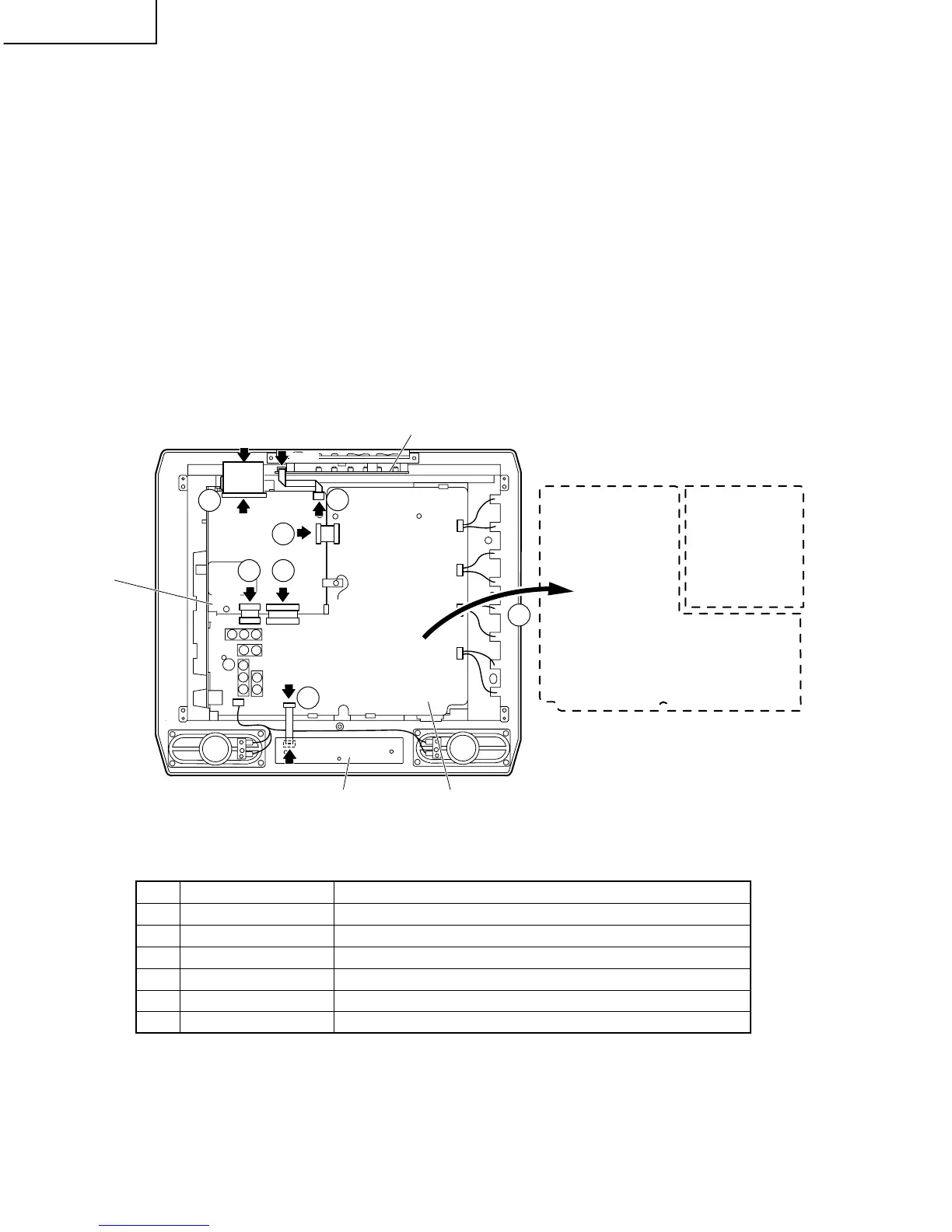
» Precautions at the time of the side-B(back) service of main and sub unit.
1. Remove the FPC for connection between Main unit (SC1701) and LCD panel (CN1), and connect the extended
cable (QCNW-C458WJQZ) for service.
2. Remove only SC1201 side of the lead from between Main unit (SC1201) and Sub unit (P7301), and connect the
extended cable (QCNW-C461WJQZ) for service.
3. Remove only SC2001 side of the lead from between Main unit (SC2001) and Sub unit (P3901), and connect the
extended cable (QCNW-C461WJQZ) for service.
4. Remove only SC2002 side of the lead from between Main unit (SC2002) and Sub unit (P3902), and connect the
extended cable (QCNW-D402WJQZ) for service.
5. Remove the FFC for connection between Main unit (SC2003) and Operation unit (SC4201), and connect the
extended cable (QCNW-D444WJQZ) for service.
6. Remove the FFC for connection between Sub unit (SC3601) and R/C, LED unit (SC4101), and connect the
extended cable (QCNW-D445WJQZ) for service.
7. Remove the PWB unit fixing screws (main unit: 2 pcs., sub unit: 2 pcs.)
Step Part No. Description
1 QCNW-C458WJQZ Extension Cable 80-pin Main (SC1701)-LCD panel (CN1)
2 QCNW-C461WJQZ Extension Cable 15-pin Main (SC1201)-Sub (P7301)
3 QCNW-C461WJQZ Extension Cable 15-pin Main (SC2001)-Sub (P3901)
4 QCNW-D402WJQZ Extension Cable 23-pin Main (SC2002)-Sub (P3902)
5 QCNW-D444WJQZ Extension Cable 5-pin Operation (SC4201)-Main (SC2003)
6 QCNW-D445WJQZ Extension Cable 8-pin R/C, LED (SC4101)-Sub (SC3601)
SC1701
SC2003
SC1201
P7301
P3902
SC2002
SC2001
P3901
SC3601
CN1
SC4201
SC4101
1
5
2
3 4
6
7
Main PWB
Operation PWB
Main PWB
(Side B)
Sub PWB
(Side B)
Sub PWB
R/C, LED PWB