6
LC-15AV6U
OPERATION MANUAL
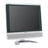
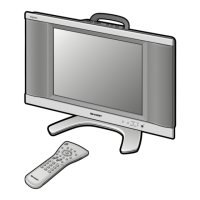
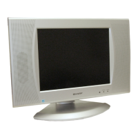
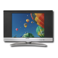
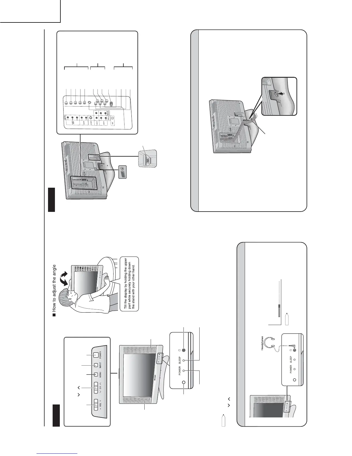
Part Names of Main Unit
The examples used throughout this manual are based on the LC-20AV6U model.
• INPUT, CH ( )/( ), VOL (–)/(+) and MENU on the main unit have the same functions as the same buttons on the remote control.
Fundamentally, this operation manual provides a description based on operation using the remote control.
Listening with Headphones
Plug the headphone mini-plug into the headphone jack
located on the side of the LCD TV set.
Adjust the sound volume using VOL (+)/(–) on the remote
control.
On-screen display
20
VOLUME
NOTE
NOTE
• Headphones are not included in the supplied accessories.
• No sound is heard from the main unit speakers when a
headphone mini-plug is connected into the headphone jack.
• Do not set the volume at a high level. Hearing experts advise
against extended listening at high volume levels.
Controls
SLEEP TIMER indicator
The SLEEP TIMER indicator lights up red when the
SLEEP TIMER is set to “ON”.
The POWER indicator lights up green
when the power is on, and red when in the
standby mode (the indicator will not light
up when the main power is off).
Headphone jack
Plug the headphone mini-plug into the headphone jack
located on the front of the main unit.
To change the vertical angle of the LCD
TV set, tilt the screen up to 2.5 degrees
forwards or 10 degrees backwards.
Please adjust the angle so that the LCD
TV set can be watched most comfortably.
Terminals
How to Fix the Cables
Be sure to secure the cables and AC cord with the supplied cable clamp.
Cable clamp
INPUT1
P
R
P
B
Y
AUDIO (L)
AUDIO (L)
S-VIDEO
VIDEO
VIDEO
AUDIO (R)
ANT. (Antenna terminal)
AUDIO (R)
AUDIO (L)
AUDIO (R)
INPUT3/OUTPUT
INPUT2
Round lock for Kensington
Security Standard slot*
AC INPUT
terminal
(AC120 V)
*
Using the Kensington Lock
• This LCD TV set has a Kensington Security Standard slot for
use with a Kensington MicroSaver Security System. Refer to
the information that came with the system for instructions on
how to use it to secure the LCD TV set.
Remote sensor
POWER indicator
Upper control panel
Speaker
POWER
INPUT
CH (Channel)
(
)/( )
VOL (Volume)
(–)/(+)
MENU
Speaker