EasyManua.ls Logo

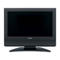
Sharp LC-26SH7E/RU

Sharp LC-26SH7E/RU
267 pages
To Next Page IconTo Next Page
Loading...
LC-19SH7E/RU, LC-26SH7E/RU, LC-32SH7E/RU, LC-42SH7E/RU
1
SERVICE MANUAL
No.
LCD COLOUR TELEVISION
LC-19SH7E/RU
LC-26SH7E/RU
LC-32SH7E/RU
MODELS LC-42SH7E/RU
In the interests of user-safety (Required by safety regulations in some countries) the set should be restored to its orig-
inal condition and only parts identical to those specified should be used.
Parts marked with " " are important for maintaining the safety of the set. Be sure to replace these parts with specified ones for maintaining the
safety and performance of the set.
This document has been published to be used for
after sales service only.
The contents are subject to change without notice.
SAFETY PRECAUTION
IMPORTANT SERVICE SAFETY PRE-
CAUTION ....................................................................2
Precautions for using lead-free solder ......………........3
CHAPTER 1. OPERATION MANUAL
[1] SPECIFICATIONS ..................................................4
[2] OPERATION MANUAL ...........................................5
[3] DIMENSIONS .......................................................10
CHAPTER 2. REMOVING OF MAJOR PARTS
[1] REMOVING OF MAJOR PARTS ..........................11
CHAPTER 3. ADJUSTMENT PROCEDURE
[1] ADJUSTMENT PROCEDURE .............................31
[2] SERVICE MODE ..................................................42
[3]
SOFTWARE UPGRADE PROCEDURE...............43
CHAPTER 4. TROUBLESHOOTING TABLE
[1] TROUBLESHOOTING TABLE..............................45
CHAPTER 5. MAJOR IC INFORMATIONS
[1] MAJOR IC INFORMATIONS.................................98
CHAPTER 6. BLOCK DIAGRAM/WIRING DIAGRAM
[1] BLOCK DIAGRAM ..............................................118
CONTENTS
[2] POWER MANAGEMENT BLOCK DIAGRAM ......120
[3] WIRING DIAGRAM ...............................................122
CHAPTER 7. PRINTED WIRING BOARD
[1] MAIN UNIT PRINTED WIRING BOARD ...............126
[2] POWER UNIT PRINTED WIRING BOARD ..........130
[3] KEY UNIT PRINTED WIRING BOARD .................134
[4] IR UNIT PRINTED WIRING BOARD ....................136
CHAPTER 8. SCHEMATIC DIAGRAM
[1] MAIN SCHEMATIC DIAGRAM ............................138
[2] POWER SCHEMATIC DIAGRAM ........................166
[3] KEY SCHEMATIC DIAGRAM ..............................169
[4] IR SCHEMATIC DIAGRAM ..................................171
CHAPTER 9. Parts Guide
[1] SPARE PARTS LIST.............................................173
[2] CABINET PARTS ..................................................250
[3] SUPPLIED ACCESSOORIES................................258
[4] PACKING PARTS..................................................259
Question and Answer IconNeed help?

Do you have a question about the Sharp LC-26SH7E/RU and is the answer not in the manual?

Sharp LC-26SH7E/RU Specifications

General IconGeneral
Screen Size26 inches
Resolution1366 x 768
Display TypeLCD
Contrast Ratio800:1
Brightness450 cd/m²
Response Time6 ms
HDMI Ports1
USB Ports1
HD Format720p
Aspect Ratio16:9
Viewing Angle176°
Input PortsComponent, Composite, SCART
Sound Output10 W (2 x 5 W)

Summary

Service Manual Contents

Important Service Safety Precautions

Crucial safety guidelines and precautions for qualified service technicians during TV repair.

Precautions for Using Lead-Free Solder

Guidelines for handling lead-free solder, including its higher melting point and wettability.

Chapter 1: Operation Manual

Details on TV specifications, operation manual, and dimensions for different models.

Chapter 2: Removing of Major Parts

Step-by-step instructions for removing major components from the TV chassis.

Chapter 3: Adjustment Procedure

Procedures for adjusting TV picture and sound settings via the OSD menu and service mode.

Chapter 4: Troubleshooting Table

A guide to diagnosing and resolving common problems with detailed troubleshooting steps.

Chapter 5: Major IC Information

Detailed information on the main integrated circuits used in the TV, including block diagrams.

Chapter 6: Block DiagramWiring Diagram

Visual representation of the TV's main board block diagram and wiring connections.

Chapter 7: Printed Wiring Board

Layout diagrams of the main unit, power unit, key unit, and IR unit printed wiring boards.

Chapter 8: Schematic Diagram

Detailed electrical schematics for the main unit and power supply circuits.

Chapter 9: Parts Guide

A comprehensive list of spare parts, including TV codes, sharp codes, and descriptions.

Related product manuals