28
LC-32G4U/G4D
LC-37G4U/G4D
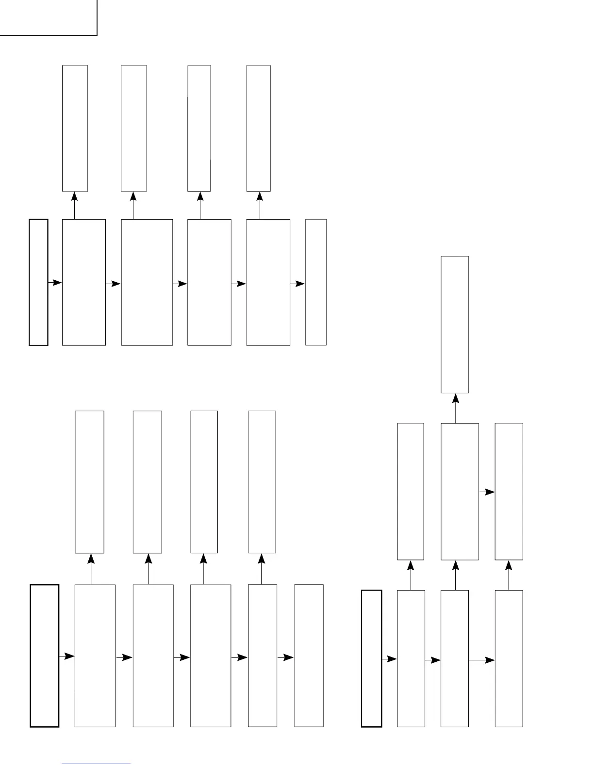
A data bit is missing.
When PATTERN1 is selected from
the adjustment process menu and it
is set to 2, is the gradation pattern
displayed correctly?
Connect SC4651 and SC4652, and
check the IC4501 peripheral circuit.
When PATTERN1 is selected from
the adjustment process menu and
PATTERN3 is set to 1, is the
gradation pattern displayed
correctly?
Check IC4702, IC4902, and their
peripheral circuits.
When PATTERN3 in the adjustment
process menu is set to 4, is the
pattern correctly displayed at one-
dot intervals?
Check between IC4701 and IC4501.
When PATTERN3 in the adjustment
process menu is set to 5, is the
pattern correctly displayed at one-
dot intervals?
Check the IC2206 peripheral circuit.
Check between IC4901 and IC4501.
No
Yes
No
Yes
No
Yes
Yes
No
When the QS driver is activated,
noise is seen in the images.
Check IC4701, IC4901, and the
peripheral circuits.
Are the GND1 PWB and the LCD
CONT PWB properly connected
with a cable?
Is the OSTEMP AD value on the
third page of the process
adjustment mode set to 255?
Connect them properly or replace
the cable.
Are the GND1 PWB and the GND2
PWB properly connected with a
board-to-board connector?
Connect them properly.
Is 5V present at pin 62 on IC2004
(the microcomputer)?
The thermistor on the GND2 PWB
is defective.
Pin 62 on IC2004 is defective.
No
Yes
No
Yes
No
Yes
Yes
No
The backlight does not light.
Has the fuse for F7401 or F7501
blown?
Check the circuits after replacing
the fuse.
Is power supplied to each inverter
PWB?
Is the control signal being output at
pins 3, 4, and 5 of P7705 on the
LCD CONT PWB?
Check the fluorescent lamp
connector and the inverter circuit.
See if the cable is connected
between PWBs.
Check the IC4501 peripheral
circuits.
Yes
Yes
Yes
Yes
No
No
No