LC-37D90U
5 – 50
2.14. RH-iXB323WJZZQ (ASSY: IC8503)
IEEE 1394a Link-Layer Controllers
• Block Diagram [RH-iXB323WJZZQ (ASSY: IC8503)]
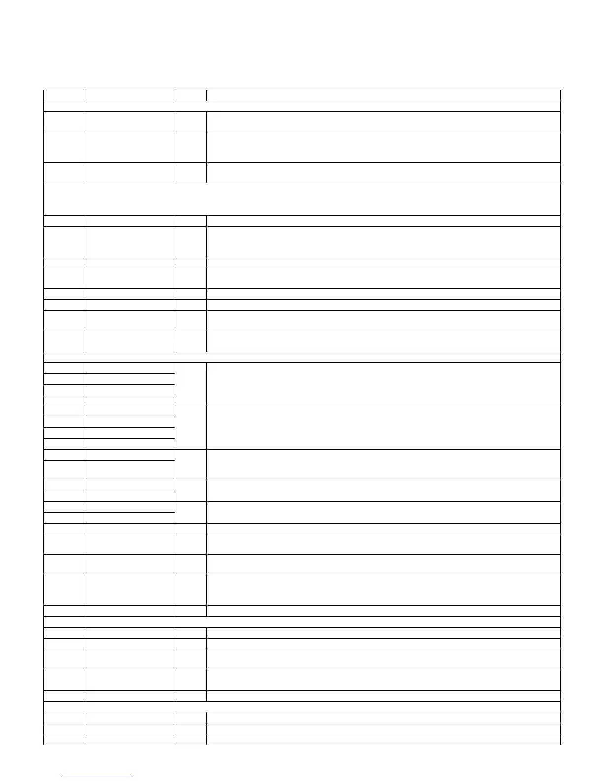
• Pin Function [RH-iXB323WJZZQ (ASSY: IC8503)]
Pin No. Pin Name I/O Pin Function
Audio PLL
F14 VCO_CLK I Input from VCO. This is used to generate internal audio clocks for receive clock recovery.
Audio frequency: 24.576MHz.
K10 REF_SYT O Output for external phase detector. This signal represents the SYT match for received audio pack-
ets. The phase detector uses it as an input to detect differences between the SYT match and the
VCO clock.
J11 DIV_VCO O Output for external phase detector. This signal is the divided VCO_CLK. It is used by the external
phase detector to compare with the REF_SYT signal. The divide ratios are set up in CFR.
Audio Interface
Note: When DAC I/F is not used, DAC_* can be directly tied to GND as long as AudCfg. Enable is set to 0.
When AudCfg. Enable to 1, DAC_* outputs are enabled.
B13 DAC_MCK O Audio master clock.
D12 DAC_BCK I/O Audio DAC Interface Bit clock.
The audio DAC interface can be used with any also path. However, only one audio stream can be
transmitted or received at one time using either the DAC interface or the 60958 interface.
D11 DAC_LRCK I/O Audio DAC Interface Left-Right Clock.
D13 DAC_DATA I/O Audio DAC Interface Data. Contains Channel 1 and Channel 2 information.
DAC_LRCK determines which channel is present.
G12 60958_IN I 60958 Bi-phase encoded data input.
H10 60958_OUT O 60958 Bi-phase encoded data output.
A12 AUDIO_ERR O Audio Error Signal. The RH-IXB323WJZZQ assert this signal whenever an audio error condition
occurs. (Receive from 1394 only.)
B14 AUDIO_MUTE O Audio Mute Signal. The RH-IXB323WJZZQ assert this signal whenever an audio error condition
occurs. (Receive from 1394 only.)
PHY Interface
A6 TPA0N I/O Twisted Pair A Differential Signal Terminals. For an unused port, TPAN and TPAP signals can be left
open.
C4 TPA1N
B6 TPA0P
B3 TPA1P
E7 TPB0N I/O Twisted Pair B Differential Signal Terminals. For an unused port, TPBN and TPBP signals should be
tied to GND.
C5 TPB1N
E6 TPB0P
B4 TPB1P
D5 TPBIAS0 I/O Twisted Pair Bias Output. These signals provide the 1.86V nominal bias voltage needed for proper
operation of the twisted pair driver and receivers for signaling an active connection to a remote
node.
A3 TPBIAS1
A1 R1 --- Current Setting Resistors.
B1 R0
E1 XI --- Crystal Oscillator Inputs. These terminals connect to a 24.576MHz parallel resonant fundamental
mode crystal.
E2 XO
B7 CPS I Cable Power Status input.
A7 CAN O Cable Not Active. This pin is asserted whenever LPS is low and a link on packet or other bus event
is received from the 1394 bus.
E8 WAKEUP O Wake-up output. This signal is asserted whenever LPS is low and a link on packet or other bus
event is received from the 1394 bus.
D8 BIASDIS I Bias Disable Function. This pin controls the PHY bias disable function at power-up and reset. The
pin value is AND-ed with the Phy Cfg. Bias Dis CFR value. When both are set to 1, the bias disable
circuits enabled. When either is set to 0, the bias disable circuit is disabled.
C11 PHY_TEST_MODEn I TI use only. This pin is low PHY testing. Should be tied high for normal operation.
Other Function
A8 PHYHCLK O PHY half clock output. 24.576MHz clock is output from this pin.
A9 PHY8CLK O PHY Eighth Clock output. Programmable clock output.
N10 RESETn I Device reset. This signal resets all logic. This includes the PHY, link core, buffers, and random logic.
The system should be able to control this signal for AKE process.
G4 RESET_HOSTn I Host Reset. In PCI mode, this signal functions as PCI RST#. It is for connection to PCI RST# on the
PCI bus.
C8 RESET_LINKn I Link Reset. Turns off clocks to all logic except PHY logic necessary for 1394 repeater mode.
JTAG Interface
L9 JTAG_TMS I JTAG Test Mode Selector pin.
K9 JTAG_TDI I JTAG Test Data Input pin.
L10 JTAG_TDO O JTAG Test Data Output pin.