
Do you have a question about the Sharp LC-37LE320 and is the answer not in the manual?
Guidelines for service technicians and safety checks.
Crucial safety information regarding circuit modifications and power disconnection.
Specific caution about replacing fuses with identical types to prevent fire risks.
Safety checks required before returning the receiver to the user.
Information on special safety-related electrical and mechanical parts and their replacement.
Advice on applying lead-free solder when fixing PWBs soldered with it.
Recommendations for soldering with lead-free solder, including temperature and tip maintenance.
Detailed technical specifications for various LCD Colour TV models.
Instructions on how to use the remote control unit and its functions.
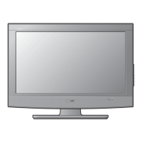
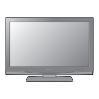
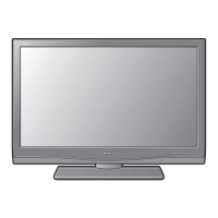
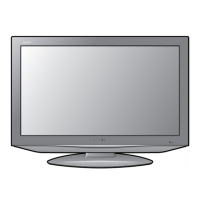
Detailed physical dimensions of the TV screen sizes.
Step-by-step guide for disassembling the 19" panel, including base removal.
Step-by-step guide for disassembling the 22" panel, including base removal.
Step-by-step guide for disassembling the 26" panel, including base removal.
Step-by-step guide for disassembling the 32" panel, including base removal.
Step-by-step guide for disassembling the 37" panel, including base removal.
Step-by-step guide for disassembling the 42" panel, including base removal.
Details on how to perform adjustments using the OSD menu.
Instructions on how to enter and navigate the factory service mode.
Step-by-step guide for upgrading firmware using USB flash drives.
Troubleshooting guide for power unit and inverter circuits for 19" models.
Troubleshooting guide for power unit operation checks for 22" models.
Troubleshooting guide for power unit operation checks for 26" models.
Troubleshooting guide for power unit operation checks for 32" models.
Troubleshooting guide for power unit operation checks for 37" models.
Troubleshooting guide for power unit operation checks for 42" models.
Detailed information about the MT5363LICG IC, including its description and key features.
Block diagram showing the function of the main board for 19"/22"/26" models.
Printed wiring board layout for the main unit of 19", 22", and 26" models (Side-A).
Printed wiring board layout for the main unit (Side-B).
Printed wiring board layout for the main unit of 32", 37", and 42" models (Side-A).
Printed wiring board layout for the main unit (Side-B).
Printed wiring board layout for the power unit (Side-A).
Printed wiring board layout for the power unit (Side-B).
Printed wiring board layout for the power unit (Side-A).
Printed wiring board layout for the power unit (Side-B).
Printed wiring board layout for the power unit (Side-A).
Printed wiring board layout for the power unit (Side-B).
Printed wiring board layout for the power unit (Side-A).
Printed wiring board layout for the power unit (Side-B).
Printed wiring board layout for the Key Unit (Side-A and Side-B).
Printed wiring board layout for the IR Unit (Side-A and Side-B).
Printed wiring board layout for the MEMC Unit (Side-A).
Printed wiring board layout for the MEMC Unit (Side-B).
Printed wiring board layout for the RS232 Unit (Side-A and Side-B).
Printed wiring board layout for the Convert Unit (AUO panel).
Printed wiring board layout for the Convert Unit (CMO panel).
Schematic diagram for the main unit of 19", 22", and 26" models.
Schematic diagram for the power supply unit (Part 1).
Schematic diagram for the power supply unit (Part 2) showing voltage regulators.
Schematic diagram for the TV tuner and its related components, including IF filters and demodulators.
Schematic showing bypass and trap circuits related to the MT5363 IC, including strapping modes.
Schematic diagrams for MT5363 peripherals and USB2.0 interface connections.
Schematics showing the DDR2 memory interface and de-coupling capacitors.
Schematic diagrams for flash memory, JTAG, UART, IR, and RS232 interfaces.
Schematic for the CI (Common Interface) card and related circuitry, including HW strapping.
Schematic diagrams for SCART and Monitor output circuits.
Schematic diagrams for YPbPr, VGA input, and SPDIF output circuits.
Schematic diagrams for HDMI1, HDMI2, and HDMI3 input circuits, including ESD protection and EDID EEPROM.
Schematic diagrams for the audio amplifier and headphone output circuits, including mute and shutdown controls.
Schematic diagrams for the LVDS output, including control signals and connectors.
Schematic diagram for the power supply unit (Part 1) for 32"/37"/42" models.
Schematic diagram for the power supply unit (Part 2) showing voltage regulators.
Schematic diagram for the TV tuner and its related components, including IF filters and demodulators.
Schematic showing bypass and trap circuits related to the MT5363 IC, including strapping modes.
Schematic diagrams for MT5363 peripherals and USB2.0 interface connections.
Schematics showing the DDR2 memory interface and de-coupling capacitors.
Schematic diagrams for flash memory, JTAG, UART, IR, and RS232 interfaces.
Schematic for the CI (Common Interface) card and related circuitry, including HW strapping.
Schematic diagrams for SCART and Monitor output circuits.
Schematic diagrams for YPbPr, VGA input, and SPDIF output circuits.
Schematic diagrams for HDMI1, HDMI2, and HDMI3 input circuits, including ESD protection and EDID EEPROM.
Schematic diagrams for the audio amplifier and headphone output circuits, including mute and shutdown controls.
Schematic diagrams for the LVDS output, including control signals and connectors.
Schematic diagram for the key input buttons on the TV.
Schematic diagram for the infrared receiver unit.
Schematic diagram for the MEMC power supply and DC converter.
Diagrams showing MT8282 peripheral interfaces, including UART, Serial Flash, and Crystal.
Diagrams illustrating LVDS transmitter and receiver connections.
Block diagram and power diagram showing the interconnectedness of major components.
Schematic diagram for the RS232 interface.
Schematic diagram for the Convert Unit (AUO panel).
Schematic diagram for the Convert Unit (CMO panel).
A comprehensive list of spare parts for the LC-19LE320E(AUO) model.
List of cabinet parts for the LC-19LE320E(AUO) model.
List of cabinet parts for the LC-22LE320E(AUO) model.
List of cabinet parts for the LC-26LE320E(AUO) model.
List of cabinet parts for the LC-32LE320E(AUO) model.
List of cabinet parts for the LC-37LE320E(AUO) model.
List of cabinet parts for the LC-42LE320E(AUO) model.
Diagram showing stand units and screws for different TV sizes.
Illustration of the AC power cord and its product shape variation.
Illustration of the remote control and AAA batteries.
Image of the Operation Manual booklet.
Image of the Quick Setup Guide booklet.
List of packing parts for the LC-19LE320E(AUO) model.
List of packing parts for the LC-22LE320E(AUO) model.
List of packing parts for the LC-26LE320E(AUO) model.
List of packing parts for the LC-32LE320E(AUO) model.
List of packing parts for the LC-37LE320E(AUO) model.
List of packing parts for the LC-42LE320E(AUO) model.





 Loading...