27
LC-32LD145
LC-39LD145
3. POWER STAGE
The DC voltages required at various parts of the chassis and panel are provided by a main power supply
unit. MB82 chassis can operate with PW05, IPS60, IPS70, IPS16, IPS17, IPS19, PW25, PW26, PW82-3,
PW03, PW04, PW06, PW07 as main power supply and also with 12V adaptor.
Which power board can be used for board to board or cable connection?
Board to board (BTB) : PW05, IPS60, IPS70, IPS16, IPS17, IPS19 Power
Cable : PW25, PW26, PW82-3, PW03, PW04, PW06, PW07
The power supplies generate 24V, 12V, 5V, 3,3V and 12V, 5V, 3.3V stand by mode DC voltages. Power
stage which is on-chassis generates 5V, 3V3 stand by voltage and 12V, 8V, 5V, 3V3, 2.5V, 1,8V and 1,2V
supplies for other different parts of the chassis. Chassis block diagram is indicated below.
The blocks on power block diagram is using dependent to main supply. For PW26 and PW27 just common
blocks are enough for proper operation.
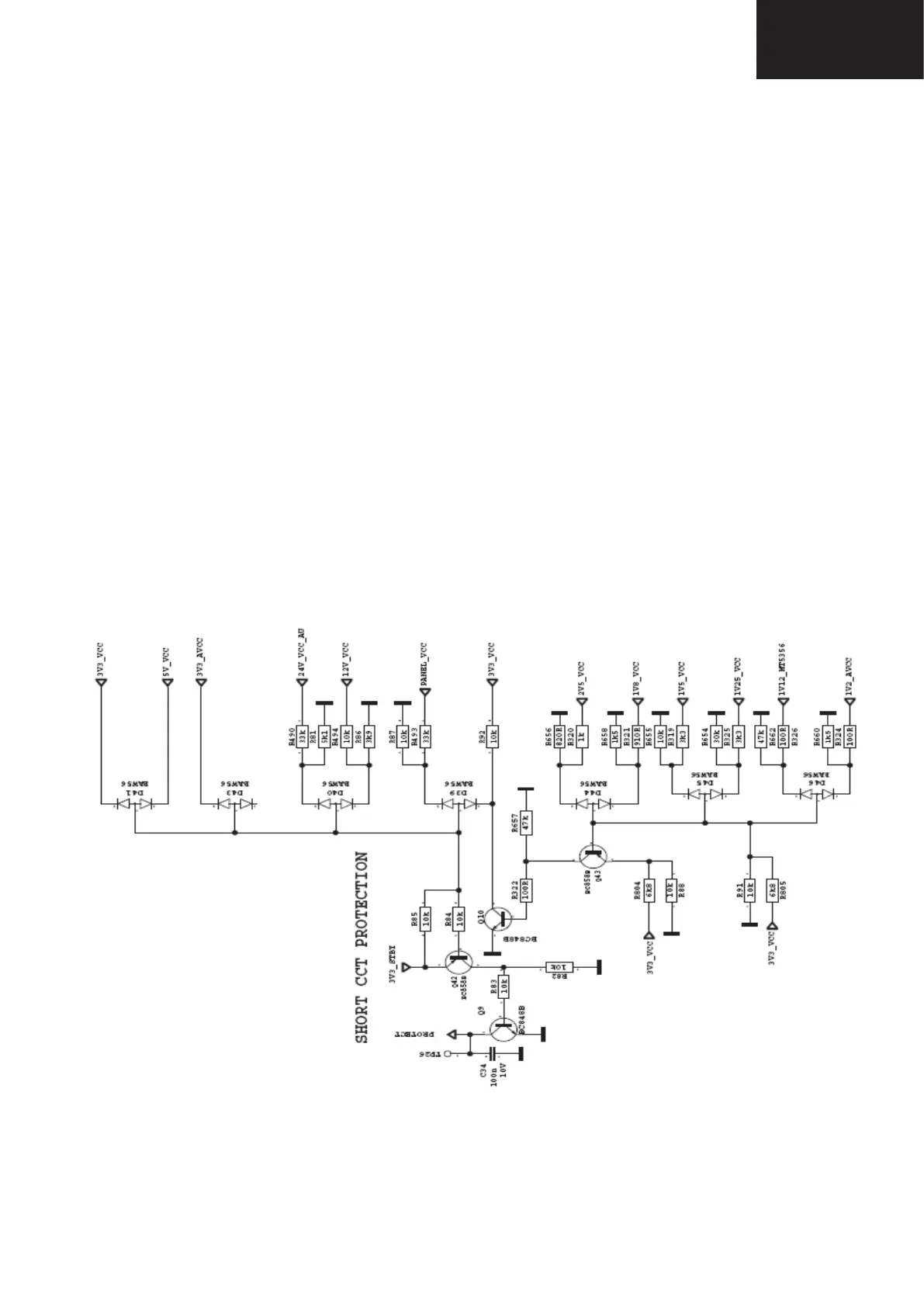
Short CCT Protection Circuit
Short circuit protection is necessary for protecting chassis and main IC against damages when any Vcc
supply shorts to ground. Protect pin should be logic high while normal operation. When there is a short circuit
protect pin shold be logic low. After any short detection, SW forces LEDs on LED card to blink.