LC-60G9T / LC-70G9T
5 – 10
9. SIGNAL ADJUSTMENT
9.1 ) LCD Adjustment [ LCD Module Adjustment ]
ERUDECORPNOITIDNOCMETI
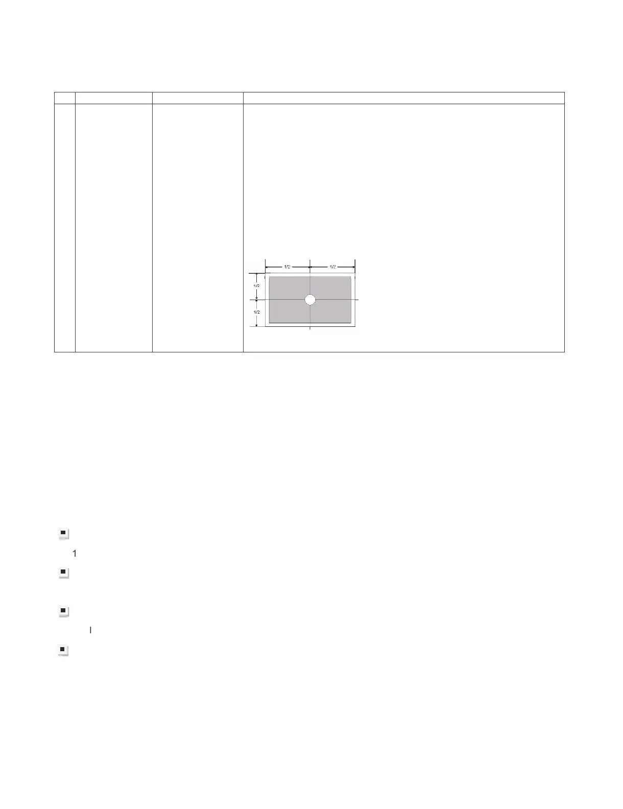
1BIAS
adjustment
(LCD module
Adjustment
Item)
Adjustment must
be done at center
of panel
1. Enter adjustment mode by using test remote control.
2. By using Remote control, press
䊺䚸䊼
to select
[VCOM ADJ]
3. After press “ENTER”, adjustment pattern will appear..
4. With key volume + / -, adjust until the flicker is minimum appear on
the center of the screen.
5. After satisfied with step 4, press “ENTER” to OFF.
[ Caution item ]
*Adjustment done during no signal from ANT (due to brightness will
change because of active backlight)
[ Adjustment Location ]
9.2) PICTURE ADJUSTMENT
(9.2.1) Equipment confirmation
Before adjustment, need to confirm that Adjustment equipment and signal generator have set to SHARP
LCD US used.
Confirmation of signal from generator (setting to spec level)
posite signal (NTSC)[For ‘T’ & ‘X’ model ] 㸸0.714Vp-p ± 0.02Vp-p (pedestal to white level)
(PAL/SECAM)[For ‘X’ model only] 㸸0.7 Vp-p ± 0.02Vp-p (pedestal to white level)
Component signal (50Hz) 㸸Y level 㸸0.7 Vp-p ± 0.02Vp-p (pedestal to white lev
el)
Pb, Pr level 㸸0.7 Vp-p ± 0.02Vp-p
Component signal 㸸Ylevel 㸸0.7 Vp-p ± 0.02Vp-p (pedestal to white level)
Pb, Pr level 㸸0.7 Vp-p ± 0.02Vp-p
ogue RGB : RGB level 㸸0.7 Vp-p ± 0.02Vp-p (pedestal to white level)