EasyManua.ls Logo

Sharp LC-60LE660U - User Manual

Sharp LC-60LE660U
72 pages
To Next Page IconTo Next Page
Loading...
SERVICE MANUAL
Parts marked with " " are important for maintaining the safety of the set. Be sure to replace these parts with specified ones for maintaining the
safety and performance of the set.
This document has been published to be used for
after sales service only.
The contents are subject to change without notice.
SAFETY PRECAUTION
IMPORTANT SERVICE SAFETY PRE-
CAUTION ............................................................i
PRECAUTIONS A PRENDRE LORS DE
LA REPARATION ...............................................ii
PRECAUTIONS FOR USING LEAD-FREE
SOLDER ........................................................... iii
OUTLINE
MAJOR SERVICE PARTS ................................iv
CHAPTER 1. SPECIFICATIONS
[1] SPECIFICATIONS ......................................... 1-1
CHAPTER 2. OPERATION MANUAL
[1] OPERATION MANUAL .................................. 2-1
CHAPTER 3. DIMENSIONS
[1] DIMENSIONS ................................................ 3-1
CHAPTER 4. REMOVING OF MAJOR PARTS
[1] REMOVING OF MAJOR PARTS (LC-
60LE660U/C6600U)....................................... 4-1
[2] REMOVING OF MAJOR PARTS (LC-
70LE660U/C6600U)....................................... 4-5
[3] The location putting on the heat measure
sheet .............................................................. 4-9
[4] Precautions for assembly............................. 4-10
CHAPTER 5. ADJUSTMENT
[1] ADJUSTMENT PROCEDURE ......................5-1
CHAPTER 6. TROUBLESHOOTING TABLE
[1] Failure diagnosis by LED in front of cabinet........6-1
[2] LED flashing specification at the time of an
error (Power and Timer icon LED used) ........6-1
[3] TROUBLESHOOTING TABLE ......................6-4
CHAPTER 7. MAJOR IC INFORMATIONS
[1] MAJOR IC INFORMATIONS .........................7-1
CHAPTER 8. OVERALL WIRING/SYSTEM BLOCK
DIAGRAM
[1] OVERALL WIRING DIAGRAM......................8-1
[2] SYSTEM BLOCK DIAGRAM.........................8-2
Parts Guide
TopPage
CONTENTS
LC-60/70LE660U,C6600U
No. S84B1LC60LE66
LC-60LE660U
LC-60C6600U
LC-70LE660U
LC-70C6600U
LCD COLOR TELEVISION
MODELS
In the interests of user-safety (Required by safety regulations in some countries) the set should be restored to its orig-
inal condition and only parts identical to those specified should be used.
1st Edition
Pravin Mevada
Pravin Mevada
Question and Answer IconNeed help?

Do you have a question about the Sharp LC-60LE660U and is the answer not in the manual?

Sharp LC-60LE660U Specifications

General IconGeneral
Screen shapeFlat
Response time- ms
Display diagonal60 \
Display brightness- cd/m²
Native aspect ratio16:9
Native refresh rate120 Hz
LED backlighting typeEdge-Lit LED
Contrast ratio (dynamic)4000000:1
Supported graphics resolutions1920 x 1080 (HD 1080)
Motion interpolation technologyAquoMotion 240
3DNo
Teletext function-
Tuner typeAnalog & digital
Analog signal format systemNTSC
Digital signal format systemATSC
RMS rated power20 W
Number of speakers2
HDMI ports quantity3
DVI-D ports quantity0
USB 2.0 ports quantity1
Wi-Fi standards802.11b, 802.11g, Wi-Fi 4 (802.11n)
On Screen Display (OSD) languagesENG, ESP, FRE
Product colorBlack
Panel mounting interface400 x 400 mm
AC input voltage110 - 240 V
AC input frequency50 - 60 Hz
Power consumption (standby)- W
Package depth200 mm
Package width1521 mm
Package height949 mm
Package weight31700 g
Sustainability certificatesENERGY STAR
Cables includedAC
Weight and Dimensions IconWeight and Dimensions
Depth (with stand)343 mm
Height (with stand)824 mm
Weight (with stand)24600 g
Depth (without stand)86 mm
Width (without stand)1355 mm
Height (without stand)781 mm
Weight (without stand)22800 g

Summary

Important Service Safety Precautions

Service Work Guidelines

Guidelines for qualified service technicians performing work.

Warning: Circuit Modification

Do not attempt circuit modifications for safety.

Caution: Fuse Replacement

Replace fuse F7001 (250V 5A) with the same type.

Receiver Safety Checks

Checks before returning receiver to user (lead dress, protective devices, leakage).

Repair Safety Precautions

Warning: Circuit Modification (French)

N'entreprendre aucune modification de tout circuit.

Caution: Fuse Replacement (French)

POUR LA PROTECTION CONTINUE CONTRE LES RISQUES D'INCENDIE, REMPLACER LE FUSIBLE.

Electrical Safety Checks (French)

Inspect wire harnesses, protective devices, and check leakage current.

Lead-Free Solder Precautions

Employing Lead-Free Solder

PWBs use lead-free solder; LF symbol indicates type.

Using Lead-Free Wire Solder

Guidelines for soldering with lead-free wire solder.

Outline and Major Service Parts

PWB Unit Major Parts

Lists main PWB units and their part codes.

Other Unit Major Parts

Lists other major units like LCD PANEL.

Service Jigs

Lists specialized connecting cords and jigs for servicing.

Chapter 1: Specifications

LCD Panel Specifications

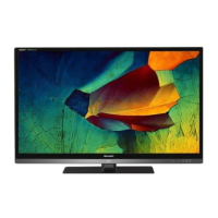
Details about panel size, resolution, and reception standards.

Audio and Terminals

Specifications for audio output and various input/output terminals.

Chapter 2: Operation Manual

Front Panel Controls

Identifies buttons on the front of the TV.

Side Panel Controls

Identifies buttons on the side of the TV.

Chapter 3: Dimensions

LC-60 LE660 U;LC-60 C6600 U Dimensions

Physical dimensions and mounting information for the 60-inch models.

Chapter 4: Removing Major Parts

Removing Major Parts (LC-60 LE660 U;C6600 U)

Guide for disassembling and removing major components for 60/70 inch models.

Removing Major Parts (LC-70 LE660 U;C6600 U)

Disassembly guide for the 70-inch model.

Heat Measure Sheet Location

Illustrates placement for heat measurement components.

Assembly Precautions

Safety and best practices during reassembly of the unit.

Chapter 5: Adjustment

Adjustment Procedure

Steps for performing adjustments after repair or for optimization.

Chapter 6: Troubleshooting Table

LED-Based Failure Diagnosis

Diagnosing issues using front LED status and flashing patterns.

Troubleshooting Table

Comprehensive table for diagnosing various TV issues.

Chapter 7: Major IC Information

Major IC Information (Model DKEYMG460 FM01)

Information on key ICs for the MAIN Unit (DKEYMG460FM01).

Major IC Information (Model DKEYMG460 FM02)

Information on key ICs for the MAIN Unit (DKEYMG460FM02).

Chapter 8: Wiring and Block Diagrams

Overall Wiring Diagram

Shows the overall internal wiring schematic of the TV.

System Block Diagram

Illustrates the functional blocks and data flow within the TV.

Sharp Parts Guide

Printed Wiring Board Assemblies

Lists all PCB assemblies used in the TV.

LCD Panel Unit

Details the LCD panel components.

Cabinet and Mechanical Parts-1 (60;70 Inch Models)

Lists mechanical parts for 60/70 inch models.

Cabinet and Mechanical Parts-2 (60;70 Inch Models)

Lists additional mechanical parts for 60/70 inch models.

Cabinet and Mechanical Parts-1 (70 Inch Models)

Lists mechanical parts for 70 inch models.

Cabinet and Mechanical Parts-2 (70 Inch Models)

Lists additional mechanical parts for 70 inch models.

Supplied Accessories;Packing Parts (60;70 Inch Models)

Lists included accessories and packing materials.

Supplied Accessories;Packing Parts (70 Inch Models)

Lists accessories for 70 inch models.

Service Jig

Lists specialized tools for servicing the unit.

Related product manuals