: Test Mode STOP
: Pre-auto adjustment menu
: ATT auto adjustment menu
: Continuous record menu
: EEPROM setting menu
: INNER switch position measurement menu
BASS
T E S T
Slide external
periphery move
Slide internal
periphery move
Tset Mode Menu
Test Mode Change Chart
A U T O 1
A U T O 2
SKIP UP SKIP DOWN
SKIP DOWN
SKIP UP SKIP DOWN
SKIP UP SKIP DOWN
SKIP UP SKIP DOWN
SKIP UP SKIP DOWN
T R E C
SKIP UP SKIP DOWN
: Continuous playback menu
T P L A Y
SKIP UP SKIP DOWN
SKIP UP SKIP DOWN
SKIP UP SKIP DOWN
: Digital input signal monitor menu
D i n M o n
SKIP UP SKIP DOWN
E E P R O M
SKIP UP SKIP DOWN
I N N E R
SKIP UP
SKIP UP
SKIP DOWN
SKIP DOWN
SKIP UP
* When the [STOP] button is pressed in specific menu, the "TEST MODE STOP" state is set.
* When the [PLAY] button operation is performed in the specific menu, the operation of this
menu is executed.
: Pre-adjustment value check menu
R S L T 1
: ATT adjustment value check menu
R S L T 2
: Pre-manual adjustment menu
M A N U 1
: ATT manual adjustment menu
M A N U 2
: Error history display menu
E D A T A
: Test mode normal playback menu
N O R M A L
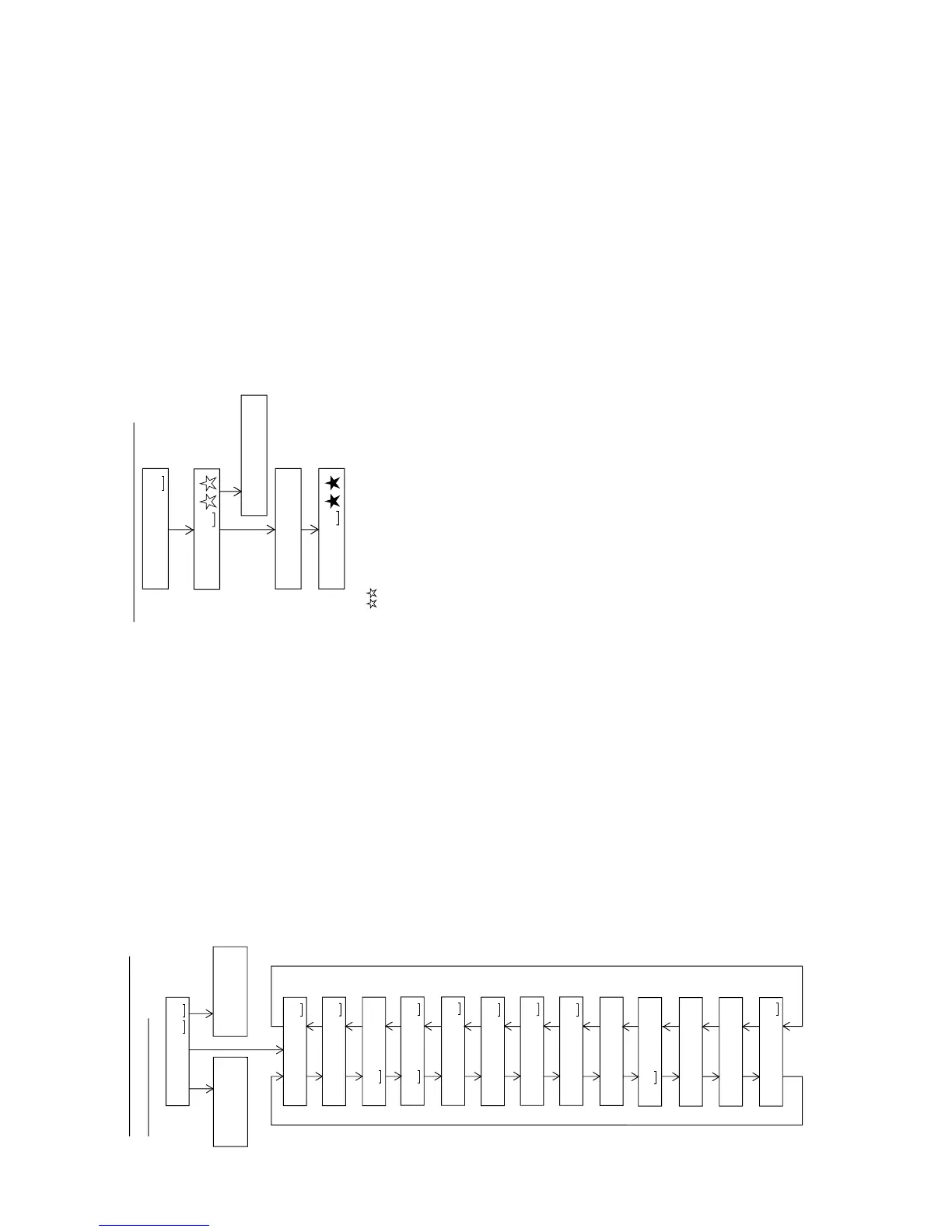
: Preautomatic Adjustment menu
: Preadjustment error (adjustment value output)
: During preadjustment adjustment
Adjustment error
Normal end
: Preadjustment normal end (adjustment value output)
: During ATT automatic adjustment
PLAY
PLAY
A U T O 1
Preautomatic Adjustment
A D J . O K
A D J . N G
A T 2
A T 1
* When the [STOP] button is pressed in specific menu, the "TEST MODE STOP" state is set.
* " " represent the adjustment number as follows.
0 0 : Innermost periphery move
0 2 : ABEF offset tentative measurement
0 4 : RF side focus gain coarse adjustment
0 5 : Focus ATT tentative setting
0 6 : RF side bit section tracking gain adjustment
0 7 : COUT level setting for pit section adjustment
0 8 : External periphery move
0 9 : RF side groove section tracking gain adjustment
1 0 : COUT level setting for groove section adjustment
1 1 : RF side TCRS gain adjustment
1 2 : Tracking ATT initial setting
1 3 : RF side focus gain minor adjustment
1 4 : Focus ATT initial setting
1 5 : S gain "High" ABEF offset measurement
1 6 : TCRS offset measurement
1 7 : S gain "Low" ABEF offset measurement