MD-MT20/20C/20W
– 43 –
Battery voltage measurement
When the battery is being used or while it is being charged, the output of pin 17 should be H (battery voltage measurement output).
The output should be held L in the power-off mode and in the other modes. However, when it is necessary to measure the battery
voltage, pull pin 17 (battery voltage measurement output) H temporarily, to make the measurement.
Charging test mode
For details about the test mode, see the separate page.
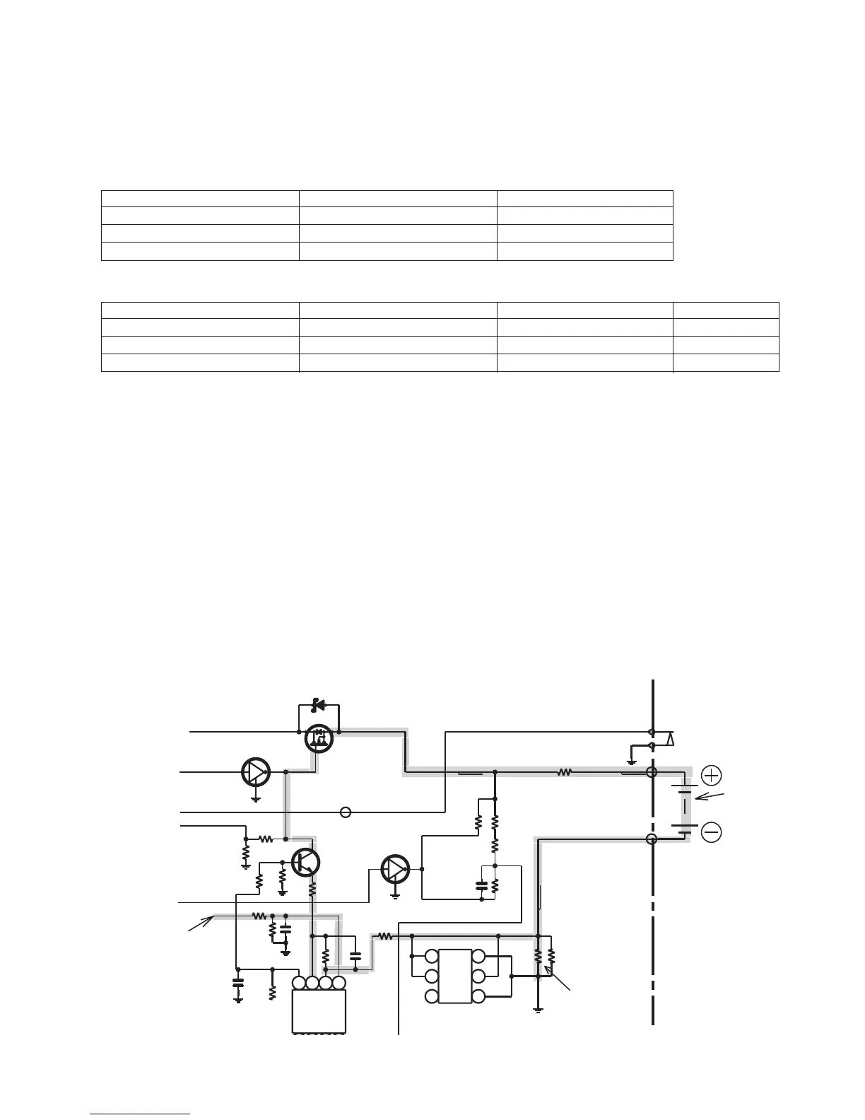
Charging circuit description
The charging current value is determined by measuring the voltage across R250/R251.
The charging current is controlled by IC805, Q252, IC803, the rechargeable battery, and R250/R251.
The reference voltage for IC401 is output from pin 85 (DA port) and is input on pin 5 on IC805.
Since the charging current is controlled by the NFB loop, the circuit is designed so that pin 5 on IC805 will have the same potential
as the voltage across R250/R251. Since R250/R251 is 0.5 ohms, the desired charging current can be obtained by varying the
potential of pin 5 on IC805.
Battery voltage measurement
The battery voltage can be measured using either of the following two modes.
1) Pin 51 on IC401 Output L
The output should always be L except during the following charging voltage measurement mode.
2) Pin 51 on IC401 Output H
The output should be H while in the charging voltage measurement mode.
Since the charging voltage is measured at intervals of five minutes while in the charging mode, the output should only be H about
500 msec every 5 minutes.
Power supply change
When one of the power supplies is selected, the port settings are as follows:
Pin 3 Charge ON output L L
Pin 85 Charging current control output Output port L Output port H
Pin 89 Battery OFF output H (1) L (3)
Port name
When operating from the AC adaptor
When operating from the battery
The port settings in the power-off mode are as follows:
Pin 3 Charge ON output L L H
Pin 85 Charging current control output Output port L Output port L 3-mode output
Pin 89 Battery OFF output H (1) L (3) L
Port name
When operating from the AC adaptor
When operating from the battery
When charging
R278
2.2K
C258
0.0047
R254
2.2K
R256
18K
R258
180K
R260
3.3M
R273
56K
Q254
RN1113
C250
0.1
R253
75K
R252
150K
D812
SB10015C
IC803
FDT439N
CHARGING
CIRCUIT
R257
100K
TP803
TP804
R804
1.0A
Q253
RN1113
TP808
R250
1
R251
1
IC806
NDC631N
6
5
4 3
2
1
R259
82K
Q252
2SC4738 GR
C254
0.1
R255
0.2M
R262
24K
R261
270K
C253
0.1
IC805
NJM022V
8
7
6
5
R270
100
VCC3
VCC4
GND1
O
-
+
+
-
O
V-
V+
G
D D
D
S
S
BATTERY
TERMINAL
SW801
Ni-MH
BATTERY
DETECTION
D
G
S
3
2
1
3
2
1
Reference voltage
input section
NFB loop
Resistor to
detect the
charging
current