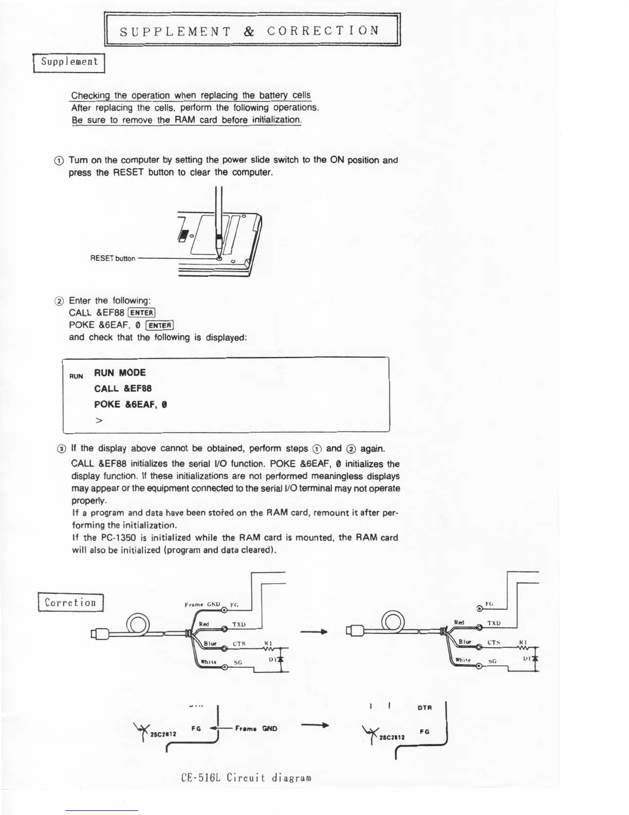
CE·5
16
L
Circuit
diagra
m
I
I
~T-R
1
'-)<
..
,.~
GND
I
FG
TF'rame
'1<2sc2112
(
SC.
HI
H
I
Blu<
C
T
S
TX
U
Corrction
Fram
e
G1'1>
F(
~
.
TXU
Ul
SC.
@
If
the display above cannot be obtained, perform steps
G)
and ® again.
CALL &EF88 initializes the serial 1/0
function
.
POKE &6EAF, 0 initializes the
display
function
.
If
these initializations are not performed meaningless displays
may appear or
t
he equipment connected to the serial 1/0 terminal may not operate
properly.
I
f
a
program
and
data
h
ave
been
stored on the RAM
ca
r
d
,
remount
it
after per-
forming the
in
iti
alization.
I
f
the
PC-
1
350
i
s
i
nitialized while the RAM card
i
s
mounted, the RAM card
will
also
be
init
i
alized (program and data
cleared
).
RUN MODE
CALL &EF88
POKE &6EAF, 9
RUN
>
® Enter the
following
:
CALL &EF88
I
ENTER
I
POKE
&6EAF
'
0
I
ENTER
I
and check that the following
is
displayed
:
RESET button
--------<!>
G)
Tum on the computer by setting the power slide switch to the ON position and
press the RESET button to clear the computer
.
Checking the operation when repladng the battery cells
After replacing the
cells
,
perform the following operations.
Be sure to remove the RAM card before
initialization
.
Supplement
II
s
u
p p
L
E
M
E
N
T
&
c
0
R R
E
c T I
0
N
II