PN-L803C/80TC3 SERVICE MENU/VARIOUS SETTING TOOL OPERATING PROCEDURES 4- 39
■ Conditions
- Viewing distance : 0.35 +/- 0.1 [m]
- Viewing angle : 0 degree and +/- 45 – 80 degree
- Criteria : visual observation
■ Background
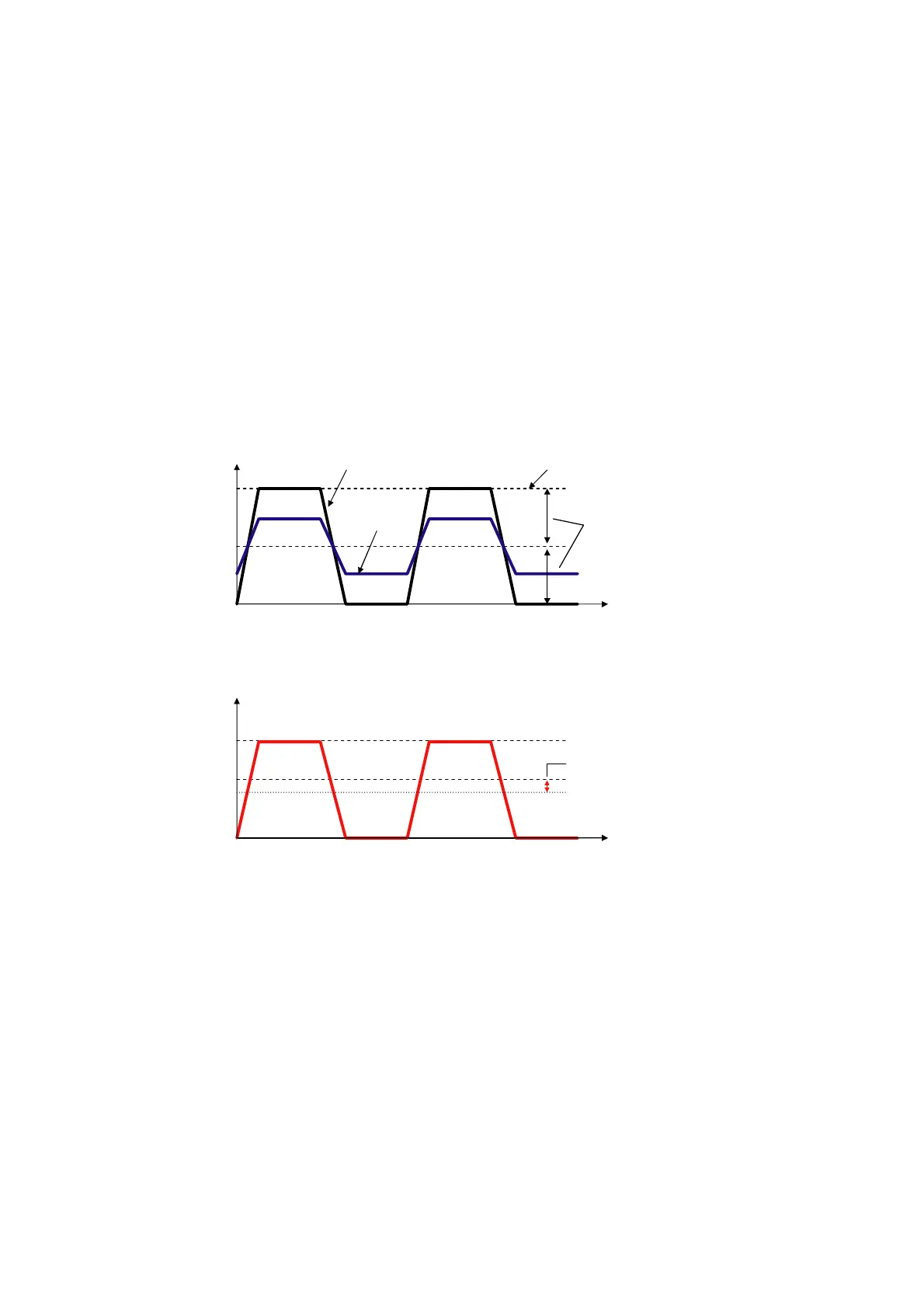
- The way of driving TFT-LCD panel is AC drive to prevent seize.
- For example AC drive is that voltage applied to TFT change from +B [V] to 0 [V] in time for 100% signal level. And the reference voltage
is +A [V] (=B/2).
- 0 [V] is not change among TFT-LCD panels.
- Though input voltage is +B [V], actual voltage applied to TFT is change among panels.
- If the reference voltage is fixed to +A [V], DC may generated. Because difference of voltage (A-0) is not equal to (B-A).
- Because DC may occur seize, the reference voltage should be adjusted with dedicated pattern to be center of 0[V] and +B[V].
- The reference voltage is called VCOM. VCOM is adjusted in flicker adjustment.
+B
+0
Voltage applied toTFT[V]
Time
+B
+0
-> Seize of LCD may occur.
waveform at
100% signal level
FIGURE SHOWS WAVEFORM OF SUITABLE VCOM VOLTAGE
+A(VCOM)
=B/2
+A(VCOM)
+B/2
These difference of voltage
must be the same.
DC is generated.
The voltage is |A-B/2|[V].
This level is changed amang
TFT - LCD panels
waveform at
50% signal level
Voltage applied toTFT[V]
FIGURE SHOWS WAVEFORM OF UNSUITABLE VCOM VOLTAGE
Time