25
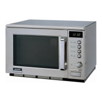
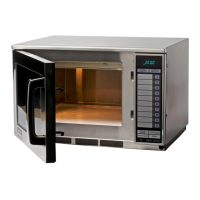
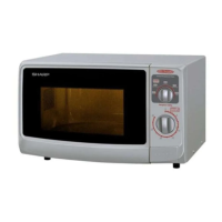
R-22AM
R-23AM
R-23AT
1 VCC IN Connected to GND.
2 VEE IN Anode (segment) of Fluorescent Display light-up voltage: -35V.
Vp voltage of power source circuit input.
3 AVSS IN Reference voltage input terminal.
A reference voltage applied to the A/D converter in the LSI. Connected to DC. (-5V)
4 VREF IN Reference voltage input terminal.
A reference voltage applied to the A/D converter in the LSI. Connected to GND.
5-6 AN7-AN6 IN Terminal to switch the specification.
7 AN5 IN Connected to GND.
8 AN4 IN A/D input for troubleshooting Magnetron 1.
9 AN3 IN A/D input for troubleshooting Magnetron 2.
10 AN2 IN Temperature measurement input: OVEN THERMISTOR (1).
By inputting DC voltage corresponding to the temperature detected by the thermis-
tor, this input is converted into temperature by the A/D converter built into the LSI.
11 AN1 IN Temperature measurement input: MAGNETRON THERMISTOR AND OVEN
THERMISTOR (2).
By inputting DC voltage corresponding to the temperature detected by the thermis-
tor, this input is converted into temperature by the A/D converter built into the LSI.
12 P60 IN Input signal which communicates the door open/close information to LSI.
Door closed; "H" level signal (0V).
Door opened; "L" level signal (-5.0V).
13 P55 OUT Power supply output at thermistor detecting circuit.
(Output -5V in cooking only, but apply high impedance to others to prevent thermistor
from electrolytic corrosion ocurrence.)
14-16 P54-P52 OUT Terminal not used.
17 P51 IN Signal coming from switch unit.
When either one of switches SW2 and SW4 on the switch unit is pressed, a
corresponding signal out of P44 and P43 will be input into P51.
18 P50 IN Signal similar to P51.
When either one of switches SW1, SW3 and SW5 on the switch unit is pressed, a
corresponding signal out of P43, P44 and P45 will be input into P50.
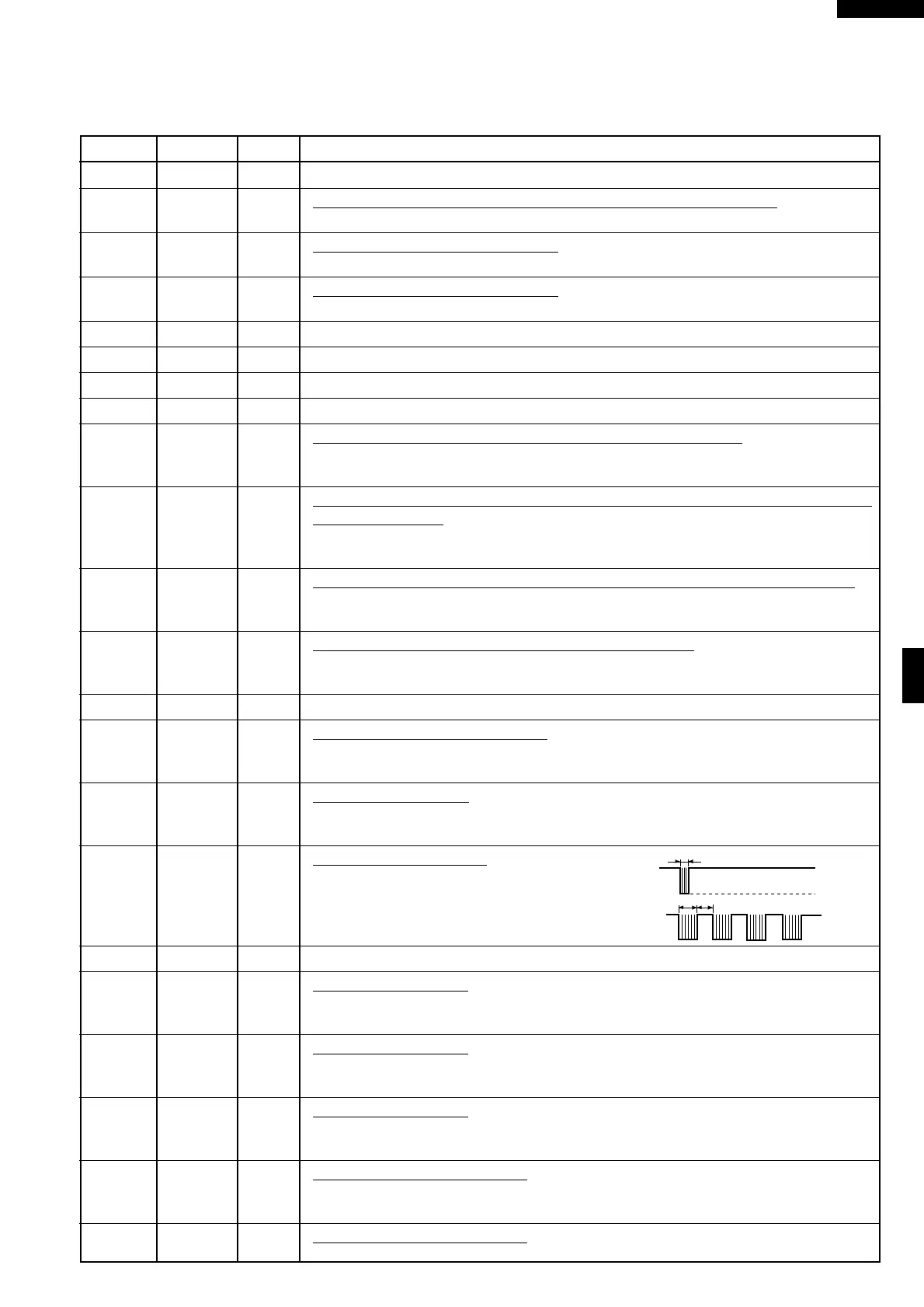
19 P47 OUT Signal to sound buzzer.
This signal is to control the 2.5kHz
continuous signal.
A: Switch touch sound.
B: Completion sound.
20 P46 OUT Terminal not used.
21 P45 OUT Switch strobe signal.
Signal is applied to the switch unit. A pulse signal is input to P50 terminal while switch
SW5 is pressed.
22 P44 OUT Switch strobe signal.
Signal is applied to the switch unit. A pulse signal is input to P50 or P51 terminal while
switch SW3 or SW4 is pressed.
23 P43 OUT Switch strobe signal.
Signal is applied to the switch unit. A pulse signal is input to P50 or P51 terminal while
switch SW1 or SW2 is pressed.
24 P42 IN Signal coming from encoder.
When the encoder is turned, the contacts of encoder make pulse signals. And pulse
signals are input into P42.
25 INT1 IN Signal coming from encoder.
Signal similar to R42. Pulse signals are input into INT1.
DESCRIPTION OF LSI FOR R-23AM / R-22AM
LSI(IZA648DR)
The I/O signal of the LSI(IZA648DR) is detailed in the following table.
Pin No. Signal I/O Description
A
B
0.12 sec
1.2 sec
1.2 sec
GND
-5V