26
R-22AM
R-23AM
R-23AT
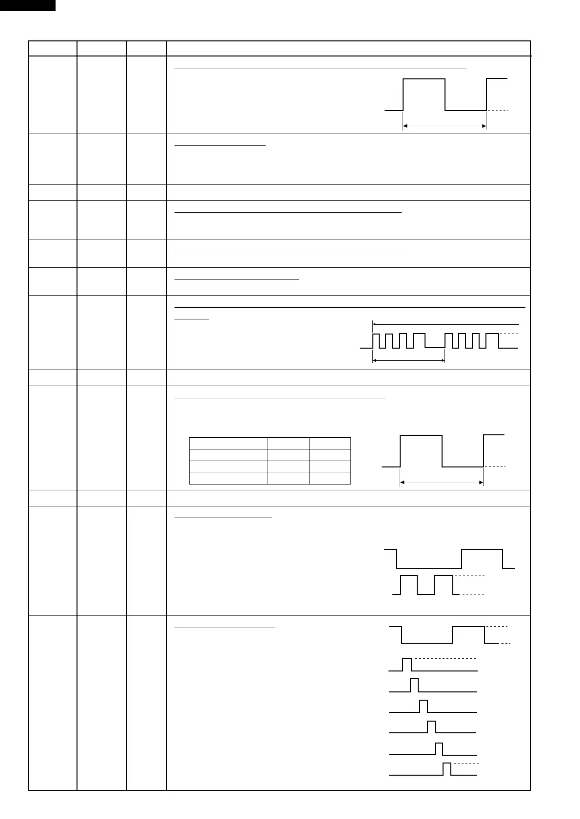
26 INT0 IN Signal synchronized with commercial power source frequency.
This is basic timing for all time processing of LSI.
27 RESET IN Auto clear terminal.
Signal is input to reset the LSI to the initial state when power is supplied. Temporarily
set to "L" level the moment power is supplied, at this time the LSI is reset. Thereafter
set at "H" level.
28-29 P71-P70 OUT Terminal not used.
30 XIN IN Internal clock oscillation frequency setting input.
The internal clock frequency is set by inserting the ceramic filter oscillation circuit with
respect to XOUT terminal.
31 XOUT OUT Internal clock oscillation frequency control output.
Output to control oscillation input of XIN.
32 VSS IN Power source voltage: -5V.
VC voltage of power source circuit input.
33 P27 OUT Oven lamp, Blower motor and Stirrer motor driving signal (Square Waveform
: 50Hz).
To turn on and off the shut-off relay (RY1).
The Square waveform voltage is delivered
to the RY1 relay driving circuit and relays
(RY2, RY3, COOK RELAY) control circuit.
34 P26 OUT Terminal not used.
35-36 P25-P24 OUT Magnetron high-voltage circuit driving signal.
To turn on and off the cook relay. In100% power level operation, "L" level during
cooking; "H" level otherwise. In other power level operation (50, 20 or 10%), "H" and
"L" level is repeated according to power level.
P0WER LEVEL ON OFF
50% 26sec. 22sec.
20% 12sec. 36sec.
10% 8sec. 40sec.
37-38 P23-P22 OUT Terminal not used.
39-48 P21-P10 OUT Segment data signal.
The relation between signals and indicators are as follows:
Signal Segment Signal Segment
P01............. i P15 ............ f
P00............. j, k P14............ e
P21............. LB P13 ............ d
P20............. UB P12 ............ c
P17............. h P11............ b
P16............. g P10............ a
49-54 P07-P02 OUT Digit selection signal.
The relation between digit signal and digit
are as follows:
Digit signal Digit
P07............. 1st.
P06............. 2nd.
P05............. 3rd.
P04............. 4th.
P03............. 5th.
P02............. 6th.
Normally, one pulse is output in every ß
period, and input to the grid of the Fluorescent
Display.
Pin No. Signal I/O Description
GND
-5V
32 sec.
OFF
ON
H
L
20 msec
During cooking
GND
-5V
48 sec.
OFF
ON
GND
-31(V)
ß(50Hz)
H
L
GND
VP
ß(50Hz)
P07
P06
P05
P04
P03
P02
GND
VP