R-380D
18
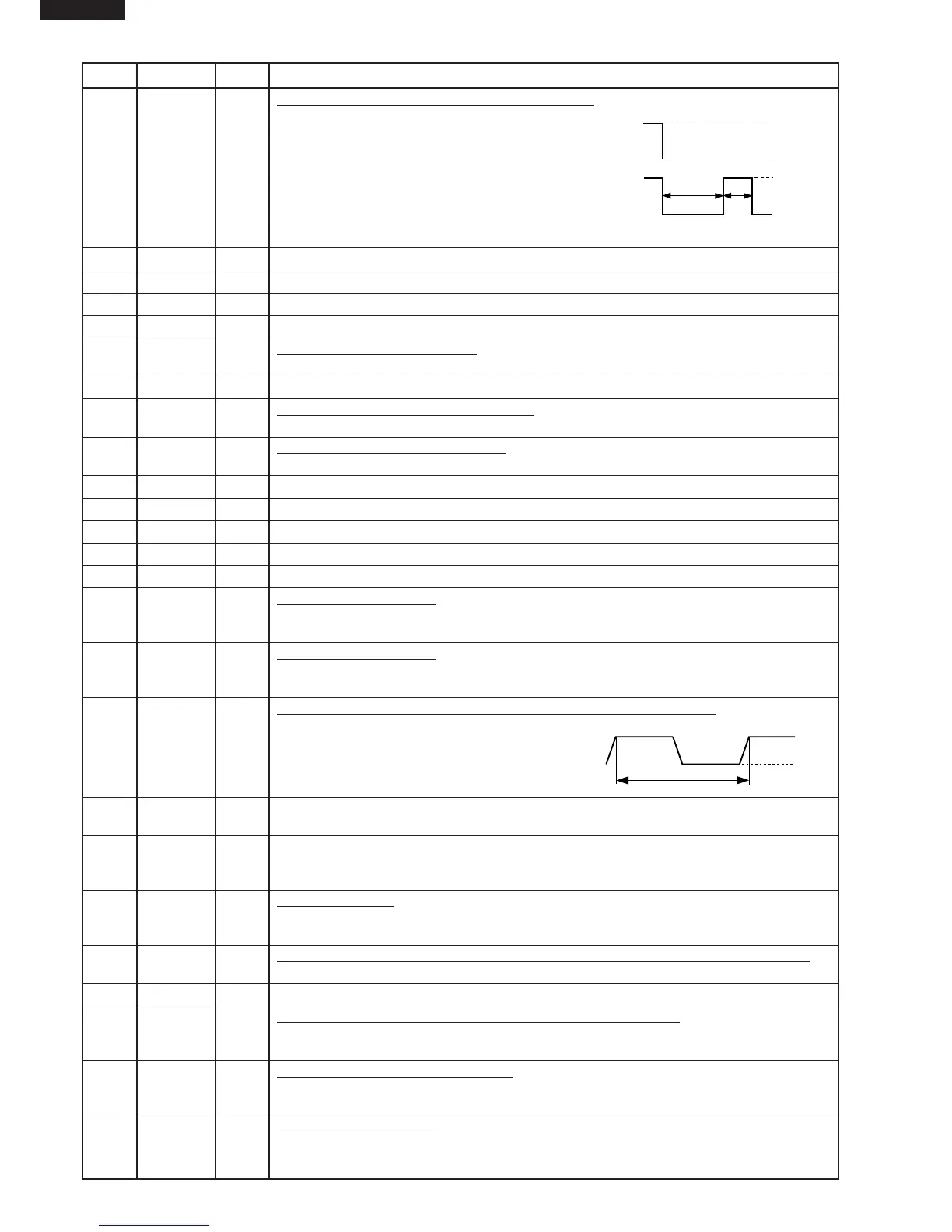
24 P25 OUT Magnetron high-voltage circuit driving signal.
To turn on and off the cook relay (RY2). The
signals holds "L" level during microwave cooking
and "H" level while not cooking. In other cooking
modes (variable cooking) the signal turns to "H"
level and "L" level in repetition according to the
power level.
(ON and OFF times for other power level.)
25-26 P26-P27 OUT Terminal not used.
27-29 P30-P32 OUT Terminal not used.
30-34 P33-P37 OUT Used for initial balancing of the bridge circuit (absolute humidity sensor).
35 CVCC IN Connected to GND.
36 VSS IN Power source voltage: -5.0V.
The power source voltage to the LSI is input to VSS terminal. Connected to VC.
37-38 V3-V2 IN Terminal not used.
39-40 V1-V0 IN Power source voltage input terminal.
Standard voltage for LCD. Connected to GND.
41 VCC IN Power source voltage: GND (0V).
The power source voltage to drive the LSI is input to VCC terminal.
42-45 COM4-COM1 OUT Terminal not used.
46-65
SEG1-SEG20
OUT Terminal not used.
66-79 P74-P91 OUT Data output terminal to LCD driver IC3.
80-85
SEG35-SEG40
OUT Terminal not used.
86 P40 OUT Terminal not used.
87 P41 IN Signal similar to AN10.
When either G13 line on key matrix is touched, a corresponding signal will be input into
P41.
88 P42 IN Signal similar to AN10.
When either G12 line on key matrix is touched, a corresponding signal will be input into
P42.
89 IRQ0 IN Signal synchronized with commercial power source frequency.
This is the basic timing for time processing of LSI.
90 AVCC IN A/D converter power source voltage.
The power source voltage to drive the A/D converter in the LSI. Connected to GND.
91 AN0 IN Used for initial balancing of the bridge circuit (absolute humidity sensor). This input is an
analog input terminal from the AH sensor circuit, and connected to the A/D converter built
into the LSI.
92 AN1 IN AH sensor input.
This input is an analog input terminal from the AH sensor circuit, and connected to the
A/D converter built into the LSI.
93 AN2 IN To input signal which communicates the door open/close information to LSI.
Door close "H" level signal (0V). Door open "L" level signal (-5V).
94 AN3 IN Connected to VC through resistor.
95-98 AN4-AN7 IN Terminal to change cooking input according to the Model.
By using the A/D converter contained in the LSI, DC voltage in accordance with the Model
in operation is applied to set up its cooking constant.
99 AN8 IN Input terminal to judge the model.
The signal out of P14 will be input into AN8 through G4 line on key matrix. The LSI will
judge the model by this signal.
100 AN9 IN Signal similar to AN10.
When either G11 line on key matrix is touched, a corresponding signal will be input into
AN9.
Pin No. Signal I/O Description
HIGH
H : GND
L : -5V
H : GND
L : -5V
M.HIGH
ON
ON
OFF
OFF OFF
24 sec.
8 sec.
20.0 msec.
H : GND
L : -5V